|
USRP Hardware Driver and Device Manual
Version: 4.10.0.0-0-g2af4ddb9
UHD and USRP Manual
|


|
|
USRP Hardware Driver and Device Manual
Version: 4.10.0.0-0-g2af4ddb9
UHD and USRP Manual
|
|
All Generation-3 USRP offer an auxiliary GPIO connection on the motherboard itself (independent of the daughterboards). These GPIO pins are controlled directly by the FPGA, where they are controlled by an ATR (Automatic Transmit / Receive). This allows them to be toggled simultaneously with other radio-level changes (e.g., enabling or disabling a TX or RX mixer).
For information on the X410 GPIO, see X4x0 GPIO API
The GPIO port is not meant to drive big loads. You should not try to source more than 5mA per pin.
The +3.3V is for ESD clamping purposes only and not designed to deliver high currents.
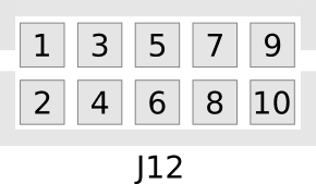
Pin 1 is connected to the shared +3.3V power rail and can be used to draw power. The maximum current depends on the power used by the rest of the device, but 300-500 mA is generally safe. It is recommended to monitor the rail voltage when drawing power from this pin.
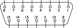
| GPIO | Mini HDMI (Type C) | HDMI (Type A) |
|---|---|---|
| Data[0] | Data 0+ - Pin 8 | Pin 7 |
| Data[1] | Data 0- - Pin 9 | Pin 9 |
| Data[2] | Clock 0+ - Pin 11 | Pin 10 |
| Data[3] | Clock 0- - Pin 12 | Pin 12 |
| Data[4] | CEC - Pin 14 | Pin 13 |
| Data[5] | SCL - Pin 15 | Pin 15 |
| Data[6] | SDA - Pin 16 | Pin 16 |
| Data[7] | Utility - Pin 17 | Pin 14 |
ATR works by defining the value of the GPIO pins for certain states of the radio. This is the "automatic" part of it. For example, you can tell UHD that when the radio is transmitting and receiving (full duplex), GPIO6 should be high, but when it is only transmitting, GPI06 should be low. This state machine is set up using a series of GPIO attributes, with paired values and a mask, which you will want to define for the GPIO pins you intend to use. To set up the ATR, you use uhd::usrp::multi_usrp::set_gpio_attr().
The counterpart to setting the ATR (the "getter"), is called uhd::usrp::multi_usrp::get_gpio_attr(). It has the exact same attributes as above, and has one more:
The front panel X3x0 GPIO bank is enumerated in the motherboard property tree (<mb_path>/gpio/FP0/\*), the E31x internal GPIO bank as (<mb_path>/gpio/INT0/\) and so are easily accessible through the standard uhd::usrp::multi_usrp UHD interface.
You can discover this using the uhd::usrp::multi_usrp::get_gpio_banks() function. This will tell you that there is a GPIO bank on your X3x0, E320, or N3x0 called "FP0" (for E31x this will be called "INT0"). This is the bank we want to set up.
Let's say we want to use GPIO6 for an external amp. We want it to be automatically controlled by ATR as an output, and we want it to be high when we are transmitting only, and low in all other cases. We are also using GPIO4, which we want to control manually, as an output. We can set this up with the following code:
After the above code is run, the ATR in the FPGA will automatically control GPIO6, as we have described, based on the radio state, and we have direct manual control over GPIO4.
To modify the example to work with the E31x's internal GPIO bank, use the bank name "INT0" instead of "FP0".
UHD allows GPIO pins to be driven or read by RFNoC blocks. For this your RFNoC block needs additional wires that get later connected to the GPIO pins like so:
This assumes you want to connect GPIO_WIDTH's pins to the block where GPIO_WIDTH is a parameter of your module. Drive gpio_ddr[i] to 1 if you want to use the pin i as an output, 0 otherwise.
Your block yaml file needs to advertise its ability to connect to GPIO pins like so:
If you block needs a fixed number of pins, it is totally fine to hard code that number in the gpio section of the io_ports.
In the image core yaml file you have to connect your block with the pins of the device and build the bitfile. Again, UHD supports connecting either all pins of a bank or a subset of it.
You have to tell the UHD software which pins are controlled by your RFNoC block. This must match your definitions in the image core yaml file. You can use either uhd::usrp::multi_usrp::set_gpio_src or uhd::rfnoc::mb_controller::set_gpio_src depending on whether you are using the multi_usrp or RFNoC API. Example: