UHD - X3x0 Series Device Manual
Table of Contents
- Comparative features list
- Getting started
- Hardware Setup
- On-Board JTAG Programmer
- Load FPGA Images onto the Device
- Load the Images onto the On-board Flash
- Setup Networking
- Addressing the Device
- Communication Problems
- Hardware Notes
- Miscellaneous
Comparative features list
- Hardware Capabilities:
- 2 transceiver card slots (can do 2x2 MIMO out of the box)
- Dual SFP+ Transceivers (can be used with 1 GigE, 10 GigE)
- PCI Express over cable (MXI) gen1 x4
- External PPS input & output
- External 10 MHz input & output
- Expandable via 2nd SFP+ interface
- Supported master clock rates: 200 MHz, 184.32 MHz
- External GPIO Connector with UHD API control
- External USB Connection for built-in JTAG debugger
- Internal GPSDO option
- Kintex-7 FPGA (X310: XC7K410T, X300: XC7K325T)
- FPGA Capabilities:
- 2 RX DDC chains in FPGA
- 2 TX DUC chain in FPGA
- Timed commands in FPGA
- Timed sampling in FPGA
- 16-bit and 8-bit sample modes (sc8 and sc16)
- Up to 120 MHz of RF bandwidth with 16-bit samples
Getting started
This will run you through the first steps relevant to get your USRP X300/X310 up and running. Here, we assume you will connect your USRP using Gigabit Ethernet (1GigE), as this interface is readily available in most computers. For 10 Gigabit Ethernet (10GigE) or PCI Express (PCIe), see the corresponding sections in this manual page.
Assembling the X300/X310 kit
Before you can start using your USRP, you might have to assemble the hardware, if this has not yet happened. Make sure you are grounded (e.g. by touching a radiator) in order not to damage sensitive electronics through static discharge!
- Unscrew the top of your X300/X310 (there are 2 screws which can be easily loosened using a small Phillips screwdriver).
- Insert the daughterboards by inserting them into the slots and optionally screwing them onto the motherboard.
- Connect the RF connectors on the daughterboards to the front panel. In order to avoid confusion, make sure the internal connections match the labels on the front panel (i.e. TX/RX is connected to TX/RX).
- If you have purchased an internal GPSDO, follow the instructions on the internal GPSDO manual page to insert the GPSDO. Note that you will need an external GPS antenna connected to the rear GPS ANT connector in order to make use of GPS, although your USRP will still be usable without.
- Connect the 1 GigE SFP+ transceiver into the Ethernet port 0 and connect the X300/X310 with your computer.
- Connect the power supply and switch on the USRP.
Network Connectivity
The next step is to make sure your computer can talk to the USRP. An otherwise unconfigured USRP device will have the IP address 192.168.10.2 when using 1GigE. It is recommended to directly connect your USRP to the computer at first, and to set the IP address on your machine to 192.168.10.1.
See the system configuration manual on details how to change your machine's IP address.
Note: If you are running an automatic IP configuration service such as Network Manager, make sure it is either deactivated or configured to not manage the network interface! This can, in extreme cases, lead to you bricking the USRP!
If your network configuration is correct, running uhd_find_devices will find your USRP and print some information about it. You will also be able to ping the USRP by running:
ping 192.168.10.2
on the command line. At this point, you should also run:
uhd_usrp_probe --args addr=192.168.10.2
to make sure all of your components (daughterboards, GPSDO) are correctly detected and usable.
Updating the FPGA Image
If the output from uhd_find_devices and uhd_usrp_probe didn't show any warnings, you can skip this step. However, if there were errors regarding the FPGA version compatibility number (compat number), you will have to upate the FPGA image before you can start using your USRP.
Download the current UHD images. You can use the uhd_images_downloader script provided with UHD (see also FPGA Image Flavors).
Use the usrp_x3xx_fpga_burner utility to update the FPGA image. On the command line, run:
usrp_x3xx_fpga_burner --addr=192.168.10.2 --type=HGS
If you have installed the images to a non-standard location, you might need to run (change the filename according to your device):
usrp_x3xx_fpga_burner --addr=192.168.10.2 --fpga-path <path_to_images>/usrp_x310_fpga_HGS.bitThe process of updating the FPGA image will take several minutes. Make sure the process of flashing the image does not get interrupted.
See Load the Images onto the On-board Flash for more details.
When your FPGA image is up to date, power-cycle the device and re-run uhd_usrp_probe. There should be no errors at this point, and all components should be correctly detected. Your USRP is now ready for development!
Hardware Setup
Gigabit Ethernet (1 GigE)
Installing the USRP X300/X310
- Prior to installing the module, the host PC can remain powered on.
- Plug a 1 Gigabit SFP Transceiver into Ethernet Port 0 on the USRP X300/X310 device.
- Use the Ethernet cable to connect the SFP+ transciever on the device to the host computer. For maximum throughput, Ettus Research recommends that you connect each device to its own dedicated Gigabit Ethernet interface on the host computer.
- Connect the AC/DC power supply to the device and plug the supply into a wall outlet.
- The OS will automatically recognize the device (e.g. when running uhd_find_devices).
Ten Gigabit Ethernet (10 GigE)
Installing the Host Ethernet Interface
Ettus Research recommends the Intel Ethernet Converged Network Adapter X520-DA2 interface for communication with the USRP X300/X310 device. Installation instructions for this interface are available on the official Intel website.
Installing the USRP X300/X310
- Prior to installing the module, the host PC can remain powered on.
- Use a 10 Gigabit SFP+ cable to connect Ethernet Port 1 on the USRP X300/X310 device to the host computer. For maximum throughput, Ettus Research recommends that you connect the device to its own dedicated Ten Gigabit, Ettus Research recommended Ethernet interface on the host computer.
- Connect the AC/DC power supply to the device and plug the supply into a wall outlet.
- The OS will automatically recognize the device (e.g. when running uhd_find_devices).
The LEDs on the front panel can be useful in debugging hardware and software issues (see Section "Front Panel")
PCI Express (Desktop)
Important Note: The USRP X-Series provides PCIe connectivity over MXI cable. We will use the 'MXI' nomenclature for the rest of this manual.
Installing the PCI Express Interface Kit
Follow the instructions listed in the Set Up Your MXI-Express x4 System document to setup the NI PCIe-8371 module.
Installing the USRP X300/X310
- Prior to installing the module, make sure that the PC is powered off.
- Using a MXI-Express Cable connect the USRP X300/X310 to the NI PCIe-8371.
- Connect the AC/DC power supply to the device and plug the supply into a wall outlet.
- Power on the USRP X300/X310 device using the power switch located in the bottom-right corner of the front panel.
- Power on the PC (The OS automatically recognizes the new device)
NOTE: The USRP device is not hot-pluggable over PCI Express. Any connection changes with only be detected by your computer after a successful reboot.
Troubleshooting
Two possible failure modes are your computer not booting when connected to your USRP device through MXI-Express, and Windows not properly discovering your devices (for example, there is a yellow exclamation point on a PCI to PCI bridge in Windows Device Manager, despite drivers for all devices being installed). These situations often are due to programming errors in PCI Express device configuration of the BIOS. To use this software, you need a MXI-Express device that supports Mode 1 operation. Refer to NI MXI-Express BIOS Compatibility Software Readme for more information.
The BIOS Compatibility Software can be downloaded for Windows from the MXI-Express BIOS Compatibility Software page
PCI Express (Laptop)
Important Note: The USRP X-Series provides PCIe connectivity over MXI cable. We will use the 'MXI' nomenclature for the rest of this manual.
Installing the PCI Express Card
Follow the instructions listed in the “Installing an NI ExpressCard-8360 Host Card” section of the Set Up Your MXI-Express x1 System document to setup the NI ExpressCard-8360B module.
Installing the USRP X300/X310
Because a laptop computer is not grounded, follow this procedure to safely connect a laptop computer to your USRP device.
- Connect the AC/DC power supply to the device and plug the supply into a wall outlet. Ensure that the USRP device is powered off.
- Touch the NI ExpressCard-8360B and a metal part of the USRP device simultaneously. Do not install the NI ExpressCard-8360B into the laptop computer yet.
- Connect the cable to the NI ExpressCard-8360B and USRP.
- Plug the NI ExpressCard-8360B into an available ExpressCard slot. If your laptop computer is already running (or hibernating, suspended, etc) when you install an NI ExpressCard-8360B, you must reboot to detect the USRP. Otherwise, the USRP is detected when you start your computer.
NOTE: The USRP device is not hot-pluggable over PCI Express. Any connection changes will only be detected by your computer after a successful reboot.
On-Board JTAG Programmer
The USRP X3x0 includes an on-board JTAG programmer, built into the motherboard. To connect to this JTAG device, simply connect your computer to the USB JTAG port on the front of the X3x0 device. You may now use the JTAG programmer in the same way you would use any other, including:
In order to use the JTAG programmer with the Xilinx tools, the Digilent drivers and plugin have to be installed first. Although recent versions of ISE ship with the driver, it has to still be manually installed.
Note: Sometimes the ISE shipped versions are newer than the ones available via Digilent's website. It is therefore advisable to use the ISE provided plugin and drivers.
To install first locate your ISE installation path (default is /opt/Xilinx/<Version>).
LINUX
sudo <ise install path>/ISE_DS/common/bin/lin64/digilent/install_digilent.sh
Afterwards either reboot or force udev to reload its rules by:
sudo udevadm control --reload
The USRP-X series device should now be usable with all the tools mentioned above.
Load FPGA Images onto the Device
The USRP-X Series device ships with a bitstream pre-programmed in the flash, which is automatically loaded onto the FPGA during device power-up. However, a new FPGA image can be configured over the PCI Express interface or the on-board USB-JTAG programmer. This process can be seen as a "one-time load", in that if you power-cycle the device, it will not retain the FPGA image.
Please note that this process is different than replacing the FPGA image stored in the flash, which will then be automatically loaded the next time the device is reset.
FPGA Image Flavors
The USRP-X Series devices contains two SFP+ ports for the two Ethernet channels. Because the SFP+ ports support both 1 Gigabit (SFP) and 10 Gigabit (SFP+) transceivers, several FPGA images are shipped with UHD to determine the behavior of the above interfaces.
| FPGA Image Flavor | SFP+ Port 0 Interface | SFP+ Port 1 Interface |
|---|---|---|
| HGS (Default) | 1 Gigabit Ethernet | 10 Gigabit Ethernet |
| XGS | 10 Gigabit Ethernet | 10 Gigabit Ethernet |
FPGA images are shipped in 2 formats:
- LVBITX: LabVIEW FPGA configuration bitstream format (for use over PCI Express and Ethernet)
- BIT: Xilinx configuration bitstream format (for use over Ethernet and JTAG)
To get the latest images, simply use the uhd_images_downloader script:
UNIX:
sudo uhd_images_downloader
Windows:
<path_to_python.exe> <install-path>/bin/uhd_images_downloader.py
Use PCI Express to load FPGA images
UHD requires a valid LabVIEW FPGA configuration bitstream file (LVBITX) to use the USRP-X Series device over the PCI Express bus. LabVIEW FPGA is NOT required to use UHD with a USRP-X Series device. Because FPGA configuration is a part of normal operation over PCI Express, there is no setup required before running UHD.
The fpga tag can be set in the optional device args passed to indicate the FPGA image flavor to UHD. If the above tag is specified, UHD will attempt to load the FPGA image with the requested flavor from the UHD images directory. If the tag is not specified, UHD will automatically detect the flavor of the image and attempt to load the corresponding configuration bitstream onto the device. Note that if UHD detects that the requested image is already loaded onto the FPGA then it will not reload it.
Use JTAG to load FPGA images
The USRP-X Series device features an on-board USB-JTAG programmer that can be accessed on the front-panel of the device. The iMPACT tool in the Xilinx Programming Tools package can be used to load an image over the JTAG interface. This can be useful for unbricking devices.
If you have iMPACT installed, you can use the impact_jtag_programmer.sh tool to install images. Make sure your X3x0 is powered on and connected to your computer using the front panel USB JTAG connector (USB 2.0 is fine for this). Then run the tool:
<path_to_uhd_tools>/impact_jtag_programmer.sh --fpga-path=<fpga_image_path>
Load the Images onto the On-board Flash
To change the FPGA image stored in the on-board flash, the USRP-X Series device can be reprogrammed over the network or PCI Express. Once you have programmed an image into the flash, that image will be automatically loaded on the FPGA during the device boot-up sequence.
Note: Different hardware revisions require different FPGA images. Determine the revision number from the sticker on the rear of the device. If you are manually specifying an FPGA path, the utility will not try to detect your device information, and you will need to use this number to select which image to burn.
Note: The burner utility will default to using the appropriate BIT file if no custom FPGA image path is specified, but it is compatible with BIN, BIT, and LVBITX images.
Use the burner tool over Ethernet
Automatic FPGA path, detect image type:
usrp_x3xx_fpga_burner --addr=<IP address>

Automatic FPGA path, select image type:
usrp_x3xx_fpga_burner --addr=<IP address> --type=<HGS or XGS>

Manual FPGA path:
usrp_x3xx_fpga_burner --addr=<IP address> --fpga-path=<path to FPGA image>
Use the burner tool over PCI Express
Automatic FPGA path, detect image type:
usrp_x3xx_fpga_burner --resource=<NI-RIO resource>

Automatic FPGA path, select image type:
usrp_x3xx_fpga_burner --resource=<NI-RIO resource> --type=<HGS or XGS>

Manual FPGA path:
usrp_x3xx_fpga_burner --resource=<NI-RIO resource> --fpga-path=<path to FPGA image>
Device recovery and bricking
It is possible to put the device into an unusable state by loading bad images ("bricking"). Fortunately, the USRP-X Series device can be loaded with a good image temporarily using the USB-JTAG interface. Once booted into the safe image, the user can once again load images onto the device over Ethernet or PCI Express.
Setup Networking
The USRP-X Series only supports Gigabit and Ten Gigabit Ethernet and will not work with a 10/100 Mbps interface.
Please note that 10 Gigabit Ethernet defines the protocol, not necessary the medium. For example, you may use 10GigE over optical with optical SFP+ transceiver modules.
Setup the host interface
The USRP-X Series communicates at the IP/UDP layer over the Gigabit and Ten Gigabit Ethernet. The default IP address for the USRP X300/X310 device depends on the Ethernet Port and interface used. You must configure the host Ethernet interface with a static IP address on the same subnet as the connected device to enable communication, as shown in the following table:
| Ethernet Interface | USRP Ethernet Port | Default USRP IP Address | Host Static IP Address | Host Static Subnet Mask | Address EEPROM key |
|---|---|---|---|---|---|
| Gigabit | Port 0 (HGS Image) | 192.168.10.2 | 192.168.10.1 | 255.255.255.0 | ip-addr0 |
| Ten Gigabit | Port 0 (XGS Image) | 192.168.30.2 | 192.168.30.1 | 255.255.255.0 | ip-addr2 |
| Ten Gigabit | Port 1 (HGS/XGS Image) | 192.168.40.2 | 192.168.40.1 | 255.255.255.0 | ip-addr3 |
As you can see, the X300/X310 actually stores different IP addresses, which all address the device differently: Each combination of Ethernet port and interface type (i.e., Gigabit or Ten Gigabit) has its own IP address. As an example, when addressing the device through 1 Gigabit Ethernet on its first port (Port 0), the relevant IP address is the one stored in the EEPROM with key ip-addr0, or 192.168.10.2 by default.
See the system configuration manual on details how to change your machine's IP address and MTU size to work well with the X300.
Multiple devices per host
For maximum throughput, one Ethernet interface per USRP is recommended, although multiple devices may be connected via an Ethernet switch. In any case, each Ethernet interface should have its own subnet, and the corresponding USRP device should be assigned an address in that subnet. Example:
Configuration for USRP-X Series device 0:
- Ethernet interface IPv4 address: 192.168.10.1
- Ethernet interface subnet mask: 255.255.255.0
- USRP-X Series device IPv4 address: 192.168.10.2
Configuration for USRP-X Series device 1:
- Ethernet interface IPv4 address: 192.168.110.1
- Ethernet interface subnet mask: 255.255.255.0
- USRP-X Series device IPv4 address: 192.168.110.2
Change the USRP's IP address
You may need to change the USRP's IP address for several reasons:
- to satisfy your particular network configuration
- to use multiple USRP-X Series devices on the same host computer
- to set a known IP address into USRP (in case you forgot)
To change the USRP's IP address, you must know the current address of the USRP, and the network must be setup properly as described above. You must also know which IP address of the X300 you want to change, as identified by their address EEPROM key (e.g. ip-addr0, see the table above). Run the following commands:
UNIX:
cd <install-path>/lib/uhd/utils
./usrp_burn_mb_eeprom --args=<optional device args> --key=ip-addr0 --val=192.168.10.3
Windows:
cd <install-path>\lib\uhd\utils
usrp_burn_mb_eeprom.exe --args=<optional device args> --key=ip-addr0 --val=192.168.10.3
Addressing the Device
Single device configuration
In a single-device configuration, the USRP device must have a unique IPv4 address on the host computer. The USRP can be identified through its IPv4 address, resolvable hostname, NI-RIO resource name or by other means. See the application notes on device identification. Use this addressing scheme with the multi_usrp interface (not a typo!).
Example device address string representation for a USRP-X Series device with IPv4 address 192.168.10.2:
addr=192.168.10.2
Example device address string representation for a USRP-X Series device with RIO resource name RIO0 over PCI Express:
resource=RIO0
Multiple device configuration
In a multi-device configuration, each USRP device must have a unique IPv4 address on the host computer. The device address parameter keys must be suffixed with the device index. Each parameter key should be of the format <key><index>. Use this addressing scheme with the multi_usrp interface.
- The order in which devices are indexed corresponds to the indexing of the transmit and receive channels.
- The key indexing provides the same granularity of device identification as in the single device case.
Example device address string representation for 2 USRPs with IPv4 addresses 192.168.10.2 and 192.168.20.2:
addr0=192.168.10.2, addr1=192.168.20.2
Communication Problems
When setting up a development machine for the first time, you may have various difficulties communicating with the USRP device. The following tips are designed to help narrow down and diagnose the problem.
RuntimeError: no control response
This is a common error that occurs when you have set the subnet of your network interface to a different subnet than the network interface of the USRP device. For example, if your network interface is set to 192.168.20.1, and the USRP device is 192.168.10.2 (note the difference in the third numbers of the IP addresses), you will likely see a 'no control response' error message.
Fixing this is simple - just set the your host PC's IP address to the same subnet as that of your USRP device. Instructions for setting your IP address are in the previous section of this documentation.
Firewall issues
When the IP address is not specified, the device discovery broadcasts UDP packets from each Ethernet interface. Many firewalls will block the replies to these broadcast packets. If disabling your system's firewall or specifying the IP address yields a discovered device, then your firewall may be blocking replies to UDP broadcast packets. If this is the case, we recommend that you disable the firewall or create a rule to allow all incoming packets with UDP source port 49152.
Ping the device
The USRP device will reply to ICMP echo requests ("ping"). A successful ping response means that the device has booted properly and that it is using the expected IP address.
ping 192.168.10.2
USRP device not enumerated (Linux)
UHD requires the RIO device manager service to be running in order to communicate with an X-Series USRP over PCIe. This service is installed as a part of the USRP RIO (or NI-USRP) installer. On Linux, the service is not started at system boot time, and is left to the user to control. To start it, run the following command:
sudo niusrprio_pcie start
If the device still does not enumerate after starting the device manager, make sure that the host computer has successfully detected it. You can do so by running the following command:
lspci -k -d 1093:c4c4
A device similar to the following should be detected:
$ lspci -k -d 1093:c4c4
04:00.0 Signal processing controller: National Instruments ...
        Subsystem: National Instruments Device 76ca
        Kernel driver in use: niusrpriok_shipped
- A USRP X300 should appear with 'Subsystem: National Instruments Device 7736'
- A USRP X310 should appear with 'Subsystem: National Instruments Device 76ca'
USRP device not enumerated (Windows)
UHD requires the RIO device manager service to be running in order to communicate with an X-Series USRP over PCIe. This service is installed as a part of the USRP RIO (or NI-USRP) installer. On Windows, it can be found in the Services section in the Control Panel and it is started at system boot time. To ensure that the service is indeed started, navigate to the Services tag in the Windows Task Manager and ensure that the status of niusrpriorpc is "Running".
If the device still does not enumerate after starting the device manager, make sure that the host computer has successfully detected it. You can do so by checking if your device shows up in the Windows Device Manager.
Monitor the host network traffic
Use Wireshark to monitor packets sent to and received from the device.
Observe Ethernet port LEDs
When there is network traffic arriving at the Ethernet port, LEDs will light up. You can use this to make sure the network connection is correctly set up, e.g. by pinging the USRP and making sure the LEDs start to blink.
Hardware Notes
Front Panel
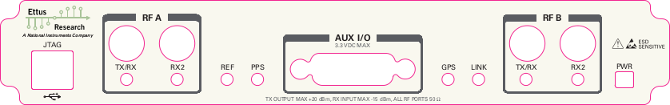
- JTAG: USB connector for the on-board USB-JTAG programmer
- RF A Group
- TX/RX LED: Indicates that data is streaming on the TX/RX channel on daughterboard A
- RX2 LED: Indicates that data is streaming on the RX2 channel on daughterboard A
- REF: Indicates that the external Reference Clock is locked
- PPS: Indicates a valid PPS signal by pulsing once per second
- AUX I/O: Front panel GPIO connector.
- GPS: Indicates that GPS reference is locked
- LINK: Indicates that the host computer is communicating with the device (Activity)
- RF B Group
- TX/RX LED: Indicates that data is streaming on the TX/RX channel on daughterboard B
- RX2 LED: Indicates that data is streaming on the RX2 channel on daughterboard B
- PWR: Power switch
Rear Panel
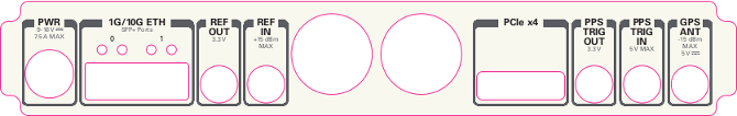
- PWR: Connector for the USRP-X Series power supply
- 1G/10G ETH: SFP+ ports for Ethernet interfaces
- REF OUT: Output port for the exported reference clock
- REF IN: Reference clock input
- PCIe x4: Connector for Cabled PCI Express link
- PPS/TRIG OUT: Output port for the PPS signal
- PPS/TRIG IN: Input port for the PPS signal
- GPS: Connection for the GPS antenna
Ref Clock - 10 MHz
Using an external 10 MHz reference clock, a square wave will offer the best phase noise performance, but a sinusoid is acceptable. The power level of the reference clock cannot exceed +15 dBm.
PPS - Pulse Per Second
Using a PPS signal for timestamp synchronization requires a square wave signal with the following a 5Vpp amplitude.
To test the PPS input, you can use the following tool from the UHD examples:
- <args> are device address arguments (optional if only one USRP device is on your machine)
cd <install-path>/lib/uhd/examples
./test_pps_input --args=<args>
Internal GPSDO
Please see the Internal GPSDO Application Notes for information on configuring and using the internal GPSDO.
Front Panel GPIO
Connector
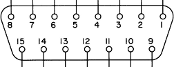
Pin Mapping
- Pin 1: +3.3V
- Pin 2: Data[0]
- Pin 3: Data[1]
- Pin 4: Data[2]
- Pin 5: Data[3]
- Pin 6: Data[4]
- Pin 7: Data[5]
- Pin 8: Data[6]
- Pin 9: Data[7]
- Pin 10: Data[8]
- Pin 11: Data[9]
- Pin 12: Data[10]
- Pin 13: Data[11]
- Pin 14: 0V
- Pin 15: 0V
Please see the GPIO API Notes for information on configuring and using the GPIO bus.
Debugging custom FPGA designs with Xilinx Chipscope
Xilinx chipscope allows for debugging custom FPGA designs similar to a logic analyzer. USRP-X series devices can be used with Xilinx chipscope using the onboard USB JTAG connector.
Further information on how to use Chipscope can be found in the Xilinx Chipscope Pro Software and Cores User Guide (UG029).
Miscellaneous
Multiple RX channels
There are two complete DDC and DUC DSP chains in the FPGA. In the single channel case, only one chain is ever used. To receive from both channels, the user must set the RX or TX subdevice specification.
In the following example, a TVRX2 is installed. Channel 0 is sourced from subdevice RX1, and channel 1 is sourced from subdevice RX2 (RX1 and RX2 are antenna connectors on the TVRX2 daughterboard).
usrp->set_rx_subdev_spec("A:RX1 A:RX2");
Available Sensors
The following sensors are available for the USRP-X Series motherboards; they can be queried through the API.
- ref_locked - clock reference locked (internal/external)
- Other sensors are added when the GPSDO is enabled