|
USRP Hardware Driver and USRP Manual
Version: 3.14.1.HEAD-0-gbfb9c1c7
UHD and USRP Manual
|


|
|
USRP Hardware Driver and USRP Manual
Version: 3.14.1.HEAD-0-gbfb9c1c7
UHD and USRP Manual
|
|
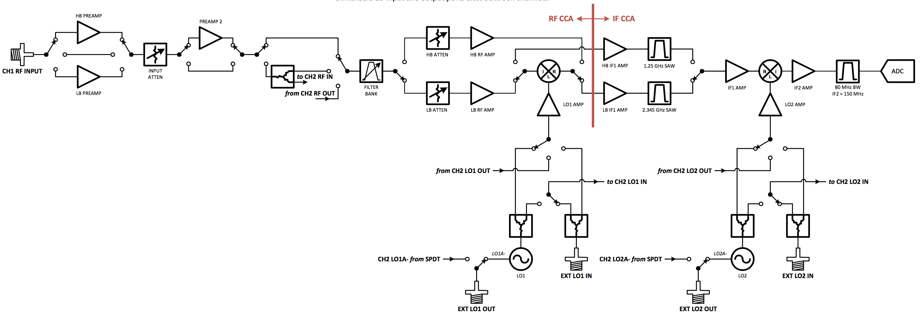
The TwinRX is a two-channel superheterodyne receiver designed for high performance spectrum monitoring and direction finding applications. The receiver is tunable from 10 MHz - 6 GHz and has 80 MHz of instantaneous bandwidth per channel, providing the versatility necessary to analyze a variety of signals in multiple bands of interest. Each channel has an independent RF signal chain with preamplifiers, preselectors, and two mixer stages for superior selectivity. Users can tune the two channels independently to simultaneously monitor uplink and downlink communication with a combined bandwidth of 160 MHz. The ability to share the LO between channels across multiple daughterboards enables the phase-aligned operation required to implement scalable multi-channel phased-arrays. The receiver is capable of fast frequency hopping to detect frequency agile emitters.
The TwinRX daughterboard only works with the X300/X310 series of USRPs.
Due to the specific configuration of the analog filters, the TwinRX can only support a master clock rate of 200 MHz. Since the X310/X300 only has a single master clock, this means that the only valid tick rate for the X300/X310 is 200 MHz, even if there is another daughterboard in the same device which could support a different tick rate.
The TwinRX uses the dual-ADC of each X300 channel to sample two separate IF streams, thus enabling two receive channels where there usually only is one. Every IF channel is sampled at 200 MHz (real sampling), and then converted to a 100 Msps complex sample stream per channel. This means the total output of one daughterboard is 2x100 Msps, which is the same aggregate sampling rate as with single-channel daughterboards such as the UBX.
The tick rate is then also halved to match the sampling rate. Timed commands are executed relative to a sample edge in the I/Q domain, i.e., at a granularity of 1/100 MHz = 10 ns.
The receive filter banks uses switches to select between the available filters. These paths are also dependent on the antenna switch settings. Incorrectly setting the switches generally results in attenuated input / output power. Receive filters are band pass (series high & low pass filters).
Source code related to controlling the filter band and antenna switches resides in twinrx_experts.cpp. Specifically, refer to the twinrx::twinrx_freq_path_expert class. Generally, these methods set the switches depending on the state of the receive streams.
The following sections provide switch setting tables for antenna and filter selection for frontend's receive paths. For further details refer to the schematics.
| Band | Range |
|---|---|
| LB1 | 10 - 500 MHz |
| LB2 | 500 - 800 MHz |
| LB3 | 800 - 1.2 GHz |
| LB4 | 1.2 - 1.8 GHz |
| HB1 | 1.8 - 3.0 GHz |
| HB2 | 3.0 - 4.1 GHz |
| HB3 | 4.1 - 5.1 GHz |
| HB4 | 5.1 - 6.0 GHz |
The TwinRX has the ability to export the two Local Oscillator (LO) signals from one channel to the companion channel on the same daughterboard and/or to one or more other TwinRXs in order to form a phase-synchronous multi-channel receiver.
| Connector | Description | Min | Nominal | Damage |
|---|---|---|---|---|
| J1 | LO2 Export | 0 dBm | 3 dBm | NA (Output) |
| J2 | LO2 Input | 0 dBm | 2 dBm | 20 dBm |
| J3 | LO1 Export | -12 dBm | 5 dBm | NA (Output) |
| J4 | LO1 Input | -10 dBm | -5 dBm | 10 dBm |
The TwinRX has two external antenna connectors (RX1 and RX2) which can be switched internally to either receiver channel. By default RX1 is connected to the first channel and RX2 to the second.
When routing the antennas in any configuration other than the default there are some behavioral changes to be aware of. As can be seen in the block diagram above the signal path from each antenna can be switched into a resistive divider and then to either or both of the receive channels. If the divider is in use the incoming signal will be slightly attenuated when compared to the direct passthrough. If both receive channels are configured to use the same antenna the first two amplifiers and are a variable attenuator are shared. The effect of this is that the first channel's gain settings for those amplifiers will override the second channel's. If both channels are tuned to the same frequency band and at similar gain settings the effect will be minimal, but if the frequency or gain difference is large the resulting gain on the second channel could be significantly lower or higher than expected. Additionally the signal path length will increase in comparison to the direct antenna mapping so the phase of the received signal will be different depending on the antenna mapping.
 1.8.13