|
USRP Hardware Driver and Device Manual
Version: 4.10.0.0-0-g2af4ddb9
UHD and USRP Manual
|


|
|
USRP Hardware Driver and Device Manual
Version: 4.10.0.0-0-g2af4ddb9
UHD and USRP Manual
|
|
The N3XX series of USRPs is designed as a platform. The following USRPs are variants of the N3XX series:

The N310 is a 4-channel transmitter/receiver based on the AD9371 transceiver IC. It has two daughterboards with one AD9371 each; every daughterboard provides two RF channels. Note that the product code "N310" refers to the module consisting of mother- and daughterboard, the daughterboard itself is referred to by its codename, "Magnesium".
The N300 is a subset of the N310. It has 2 TX/RX channels (on a single daughterboard; the daughterboard itself is the same as the N310) and a smaller FPGA (XCZ035). Also, it does not have connectors for external LOs.
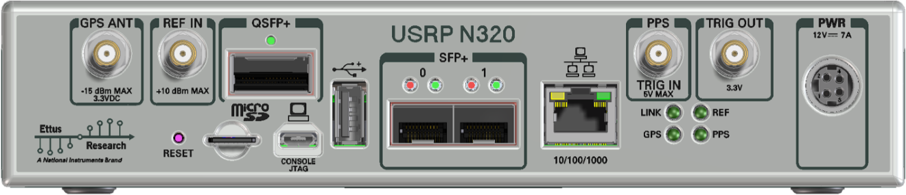
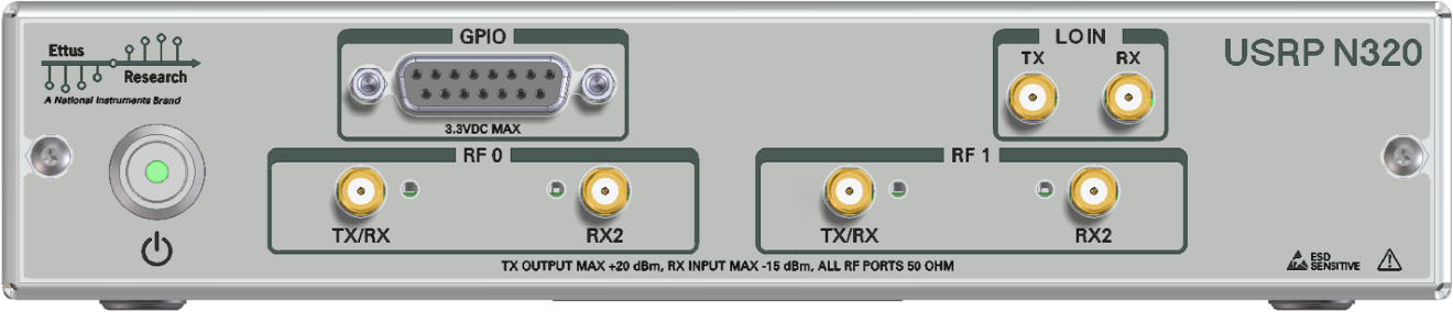
The N320 is a 2-channel transmitter/receiver using discrete components instead of an RFIC. It has two daughterboards, each has one ADC/DAC and provides one RF channel.
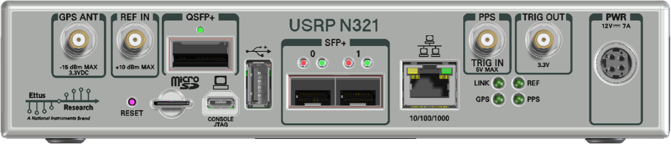
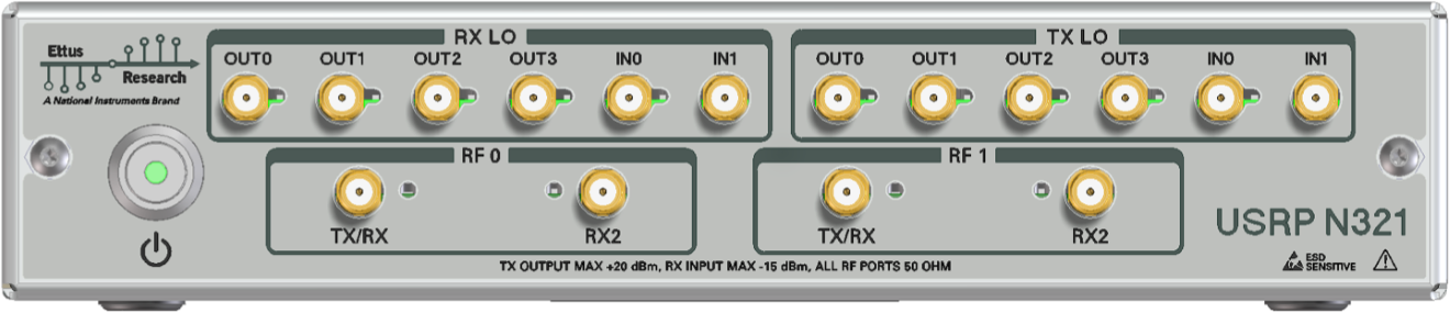
The difference between the N320 and the N321 is in its LO sharing capability. The N320 has a single input for the TX and RX LOs, respectively. The N321 also has the ability to export its LO up to four times, making it possible to share LOs between a large number of N321 devices without having to provide an external, separate LO source. Due to number of connectors required to provide the large number of LO outputs, the N321 does not have a front-panel GPIO connector.
The N320 has a higher maximum analog bandwidth than the N310. It can provide rates up to 250 Msps, resulting in a usable analog bandwidth of up to 200 MHz. In order to better use the high available rates, the N320/N321 devices have an additional QSFP+ connector on the back panel which can be used for streaming data to and from the radios. In order to facilitate the higher bandwidth, UHD uses a technology called Data Plane Development Kit (DPDK). See the DPDK page for details on how it can improve streaming, and how to use it.
The main CPU of the N310 is a Xilinx Zynq SoC XC7Z100 (exception: The N300). It is both a dual-core ARM Cortex A9 CPU and Kintex-7 FPGA on a single die. The CPU is clocked at 800 MHz (speedgrade 2).
The programmable logic (PL, or FPGA) section of the SoC is responsible for handling all sampling data, the 10 GigE network connections, and any other high-speed utility such as custom RFNoC logic. The processing system (PS, or CPU) is running a custom-build OpenEmbedded-based Linux operating system. The OS is responsible for all the device and peripheral management, such as running MPM, configuring the network interfaces, running local UHD sessions, etc.
It is possible to connect to the host OS either via SSH or serial console (see sections SSH connection and Serial connection, respectively).
The STM32 microcontroller controls various low-level features of the N3xx series motherboard: It controls the power sequencing, reads out fan speeds and some of the temperature sensors. It is connected to the Zynq via an I2C bus.
It is possible to log into the STM32 using the serial interface (see Connecting to the microcontroller). This will allow certain low-level controls, such as remote power cycling should the CPU have become unresponsive for whatever reason.
The N3XX series uses a micro SD card as its main storage. The entire root file system (Linux kernel, libraries) and any user data are stored on this SD card.
The SD card is partitioned into four partitions:
Note: It is possible to access the currently inactive root file system by mounting it. After logging into the device using serial console or SSH (see the following two sections), run the following commands:
$ mkdir temp
$ mount /dev/mmcblk0p3 temp
$ ls temp # You are now accessing the idle partition:
bin   data  etc   lib         media  proc  sbin  tmp    usr
boot  dev   home  lost+found  mnt    run   sys   uboot  var
The device node in the mount command will likely differ, depending on which partition is currently already mounted.
This will run you through the first steps relevant to getting your USRP N3XX series up and running.
Unlike the X300 or N200 series, there is no assembly of daughterboards required. Members of the N3XX product family, such as the N310, ship with daughterboards pre-installed.
Checklist:
Before doing any major work with a newly acquired USRP N3XX, it is recommended to update the file system. There are two methods to accomplish this:
The external method is recommended for updating devices from the factory-default file system version 3.x to file system versions greater than v4.6.
The first step of the external method is to obtain the necessary file system image. To acquire the default micro SD card image for a specific version of UHD, follow these steps:
$ uhd_images_downloader -t n3xx_common_sdimg_default
The image will be downloaded to <UHD_INSTALL_DIR>/share/uhd/images/usrp_n3xx_fs.sdimg, where <UHD_INSTALL_DIR> is the UHD installation directory.
-i option to specify a download folder where you have write access.To load an image onto the micro SD card, connect the card to the host and run:
$ sudo dd if=<YOUR_IMAGE> of=/dev/<YOUR_SD_CARD> bs=1M
The <YOUR_IMAGE> is the path to the micro SD card image (i.e.<UHD_INSTALL_DIR>/share/uhd/images/usrp_n3xx_fs.sdimg).
The <YOUR_SD_CARD> device node depends on your operating system and which other devices are plugged in. Typical values are sdb or mmcblk0.
CAUTION: Operating on the wrong device can cause damage to that device.
Manual loading a file system image on to micro SD card is straight forward on Windows with the use of 3rd party utilities available online. One is the open source, cross-platform utility Etcher, that is also available for macOS and X86 Linux. Follow the steps to load image on the micro SD card:
The micro SD card used can be the original SD card shipped with the device or another one that is at least 16 GB in size.
Insert the updated micro SD card and power on the device.
It is possible to gain root access to the device using a serial terminal emulator. Most Linux, OSX, or other Unix flavours have a tool called 'screen' which can be used for this purpose, by running the following command:
$ sudo screen /dev/ttyUSB2 115200
In this command, we prepend 'sudo' to elevate user privileges (by default, accessing serial ports is not available to regular users), we specify the device node (in this case, /dev/ttyUSB2), and the baud rate (115200).
The exact device node depends on your operating system's driver and other USB devices that might be already connected. Modern Linux systems offer alternatives to simply trying device nodes; instead, the OS might have a directory of symlinks under /dev/serial/by-id:
$ ls /dev/serial/by-id
usb-Digilent_Digilent_USB_Device_25163511FE00-if00-port0
usb-Digilent_Digilent_USB_Device_25163511FE00-if01-port0
usb-Silicon_Labs_CP2105_Dual_USB_to_UART_Bridge_Controller_007F6CB5-if00-port0
usb-Silicon_Labs_CP2105_Dual_USB_to_UART_Bridge_Controller_007F6CB5-if01-port0
Note: Exact names depend on the host operating system version and may differ.
Every N3XX series device connected to USB will by default show up as four different devices. The devices labeled "USB_to_UART_Bridge_Controller" are the devices that offer a serial prompt. The first (with the if00 suffix) connects to Linux, whereas the second connects to the STM32 microcontroller. If you have multiple N3XX devices connect, you may have to try out multiple devices. In this case, to use this symlink instead of the raw device node address, modify the command above to:
$ sudo screen /dev/serial/by-id/usb-Silicon_Labs_CP2105_Dual_USB_to_UART_Bridge_Controller_007F6CB5-if00-port0 115200
You should be presented with a shell prompt similar to the following:
root@ni-n3xx-311FE00:~#
On this prompt, you can enter any Linux command available. Using the default configuration, the serial console will also show all kernel log messages (unlike when using SSH, for example), and give access to the boot loader (U-boot prompt). This can be used to debug kernel or bootloader issues more efficiently than when logged in via SSH.
The STM32 microcontroller (which controls the power sequencing, among other things) also has a serial console available. To connect to the microcontroller, use the other UART device. In the example above:
$ sudo screen /dev/serial/by-id/usb-Silicon_Labs_CP2105_Dual_USB_to_UART_Bridge_Controller_007F6CB5-if01-port0 115200
It provides a very simple prompt. The command 'help' will list all available commands. A direct connection to the microcontroller can be used to hard-reset the device without physically accessing it (i.e., emulating a power button press) and other low-level diagnostics.
The USRP N-Series devices have two network connections: The dual SFP ports, and an RJ-45 connector. The latter is by default configured by DHCP; by plugging it into into 1 Gigabit switch on a DHCP-capable network, it will get assigned an IP address and thus be accessible via ssh.
In case your network setup does not include a DHCP server, refer to the section Serial connection. A serial login can be used to assign an IP address manually.
After the device obtained an IP address you can log in from a Linux or OSX machine by typing:
$ ssh root@ni-n3xx-311FE00 # Replace with your actual device name!
Depending on your network setup, using a .local domain may work:
$ ssh [email protected]
Of course, you can also connect to the IP address directly if you know it (or set it manually using the serial console).
Note: The device's hostname is derived from its serial number by default (ni-n3xx-$SERIAL). You can change the hostname by creating the file /data/network/hostname, saving the desired hostname in it, then rebooting.
On Microsoft Windows, the connection can be established using a tool such as Putty, by selecting a username of root without password.
Like with the serial console, you should be presented with a prompt like the following:
root@ni-n3xx-311FE00:~#
The RJ45 port (eth0) comes up with a default configuration of DHCP, that will request a network address from your DHCP server (if available on your network).
The SFP+ (sfp0, sfp1) ports are configured with static addresses 192.168.10.2/24 and 192.168.20.2/24, respectively. Their default MTU value is 9000. These settings are independent of the image type (HG vs. XG), i.e., the defaults are the same for 1 GigE and 10 GigE (unlike the X310!).
The configuration for the sfpX port is stored in /data/network/sfpX.network.
For configuration please refer to the systemd-networkd manual pages
The factory settings are as follows:
eth0 (DHCP):

    [Match]
    Name=eth0

    [Network]
    DHCP=v4

    [DHCPv4]
    UseHostname=false

sfp0 (static):

    [Match]
    Name=sfp0

    [Network]
    Address=192.168.10.2/24

    [Link]
    MTUBytes=9000

sfp1 (static):

    [Match]
    Name=sfp1

    [Network]
    Address=192.168.20.2/24

    [Link]
    MTUBytes=9000
Additional notes on networking:
/data/network/sfp0.network~), that systemd-networkd might accidentally pick up.ifconfig or other command line tools will only change the value until the next reboot or reload of the FPGA image.The N3XX ships without a root password set. It is possible to ssh into the device by simply connecting as root, and thus gaining access to all subsystems. To set a password, run the command
$ passwd
on the device.
Updating the FPGA follows the same procedure as other USRPs. Use the uhd_image_loader command line utility to upload a new FPGA image onto the device.
A common reason to update the FPGA image is in the case of a UHD/FPGA compat number mismatch (for example, if UHD has been updated, and now expects a newer version of the FPGA than is on the device). In this case, simply run
$ uhd_images_downloader
to update the local cache of FPGA images. Then, run
$ uhd_image_loader --args type=n3xx,addr=ni-n3xx-311fe00
to update the FPGA using the default settings. If a custom FPGA image is targeted for uploading, use the --fpga-path command line argument. Run
$ uhd_image_loader --help
to see a full list of command line options. Note that updating the FPGA image will force a reload of the FPGA, which will temporarily take down the SFP network interfaces (and temporary settings, such as applied via ifconfig on the command line, will be lost).
The USRP-N300 Series devices contains two SFP+ ports for the two Ethernet channels. Because SFP+ ports can be used for either 1 Gigabit (SFP) or 10 Gigabit (SFP+) transceivers, several FPGA images are shipped with UHD to determine the behavior of the above interfaces.
Interfaces can be used for either 1 Gigabit Ethernet, 10 Gigabit Ethernet, Aurora (using 10 Gigabit speeds), and White Rabbit (the White Rabbit interface does not support streaming, it only provides a time reference). See also White Rabbit. We provide the following flavors of FPGA images in our default image set:
| FPGA Image Flavor | SFP+ Port 0 Interface | SFP+ Port 1 Interface |
|---|---|---|
| HG (Default) | 1 Gigabit Ethernet | 10 Gigabit Ethernet |
| XG | 10 Gigabit Ethernet | 10 Gigabit Ethernet |
| HA | 1 Gigabit Ethernet | Aurora |
| XA | 10 Gigabit Ethernet | Aurora |
| AA | Aurora | Aurora |
| WX | White Rabbit | 10 Gigabit Ethernet |
The N320 has an additional QSFP port, and therefore has additional FPGA flavors (AQ, XQ). For more information on those, see SFP+ and QSFP+ protocols.
Like any other USRP, all N3XX USRPs are controlled by the UHD software. To integrate a USRP N3XX into your C++ application, you would generate a UHD device in the same way you would for any other USRP:
For a list of which arguments can be passed into make(), see Section Device arguments.
| Key | Description | Supported Devices | Example Value |
|---|---|---|---|
| addr | IPv4 address of primary SFP+ port to connect to. | All N3xx | addr=192.168.30.2 |
| second_addr | IPv4 address of secondary SFP+ port to connect to. | All N3xx | second_addr=192.168.40.2 |
| mgmt_addr | IPv4 address or hostname which to connect the RPC client. Defaults to ‘addr’. | All N3xx | mgmt_addr=ni-sulfur-311FE00 (can also go to RJ45) |
| find_all | When using broadcast, find all devices, even if unreachable via CHDR. | All N3xx | find_all=1 |
| force_reinit | Force full reinitialization of all subsystems. Will increase init time. | N310 | force_reinit=1 |
| master_clock_rate | Master Clock Rate in Hz | N310 | master_clock_rate=125e6 |
| identify | Causes front-panel LEDs to blink. The duration is variable. | N310 | identify=5 (will blink for about 5 seconds) |
| serialize_init | Force serial initialization of motherboards. | All N3xx | serialize_init=1 |
| skip_init | Skip the initialization process for the device. | All N3xx | skip_init=1 |
| time_source | Specify the time (PPS) source. | All N3xx | time_source=internal |
| clock_source | Specify the reference clock source. | All N3xx | clock_source=internal |
| ref_clk_freq | Specify the external reference clock frequency, default is 10 MHz. | N310 | ref_clk_freq=20e6 |
| init_cals | Specify the bitmask for initial calibrations of the RFIC. | N310 | init_cals=BASIC |
| init_cals_timeout | Timeout for initial calibrations in milliseconds. | N310 | init_cals_timeout=45000 |
| discovery_port | Override default value for MPM discovery port. | All N3xx | discovery_port=49700 |
| rpc_port | Override default value for MPM RPC port. | All N3xx | rpc_port=49701 |
| tracking_cals | Specify the bitmask for tracking calibrations of the RFIC. | N310 | tracking_cals=ALL |
| rx_lo_source | Initialize the source for the RX LO. | N310 | rx_lo_source=external |
| tx_lo_source | Initialize the source for the TX LO. | N310 | tx_lo_source=external |
| rfic_digital_loopback | Digital data loopback inside the RFIC. | N310 | rfic_digital_loopback=1 |
| tx_gain_profile | Initialize device with a specific TX gain profile. | N310 | tx_gain_profile=manual |
| rx_gain_profile | Initialize device with a specific RX gain profile. | N310 | rx_gain_profile=manual |
| tx_band_map | Semicolon-separated list of TX band edges. | N310 | tx_band_map=0.0;723.18e6;1623.18e6;3323.18e6 |
| rx_band_map | Semicolon-separated list of RX band edges. | N310 | rx_band_map=0.0;431e6;601e6;1051e6;1601e6;2101e6;2701e6 |
| force_mtu | Skips MTU detection and manually sets a network MTU. | All N3xx | force_mtu=8000 |
To maximally speed up UHD, an initialization sequence is run when the device (or more accurately, the MPM service) starts. This means even on the first run of UHD, the device will already be initialized into a usable state. Note that it will always come up in a default state, which can be changed by modifying the configuration file in /etc/uhd/mpm.conf (see also Configuration Files), such as this:
If you prefer not to have the device initialize on boot, but rather have a fast boot time, add the line skip_boot_init=1 to your /etc/uhd/mpm.conf file. This will force a full initialization of the device the first time a UHD session is started, rather than during device boot.
For more details on the initialization sequence, see the corresponding section for the specific N3XX device:
The RF ports on the front panel of the N300/N310 correspond to the following subdev specifications:
| Label | Subdev Spec |
|---|---|
| RF0 | A:0 |
| RF1 | A:1 |
| RF2 | B:0 (N310 only) |
| RF3 | B:1 (N310 only) |
The RF ports on the front panel of the N320/N321 correspond to the following subdev specifications:
| Label | Subdev Spec |
|---|---|
| RF0 | A:0 |
| RF1 | B:0 |
Note: Before UHD 3.12.0.0, the subdev spec options were different (A:0, B:0, etc.). Make sure to update your application if you migrated from an earlier UHD version.
The following example will map RF0 onto channel 0 of a uhd::usrp::multi_usrp object, and RF3 onto channel 1:
See also uhd::usrp::subdev_spec_t.
Like other USRPs, the N3x0 series have daughterboard and motherboard sensors. When using uhd::usrp::multi_usrp, the following API calls are relevant to interact with the sensor API:
The following motherboard sensors are always available:
ref_locked: This will check that all the daughterboards have locked to the external reference.temp: The temperature of the die itselffan: The current fan speedgps_locked: GPS lockgps_time: GPS time in seconds sin ce the epchgps_tpv: A TPV report from GPSd serialized as JSONgps_sky: A SKY report from GPSd serialized as JSONMender is a third-party software that enables remote updating of the root file system without physically accessing the device (see also the Mender website). Mender can be executed locally on the device, or a Mender server can be set up which can be used to remotely update an arbitrary number of USRP devices. Mender servers can be self-hosted, or hosted by Mender (see mender.io for pricing and availability).
When updating the file system using Mender, the tool will overwrite the root file system partition that is not currently mounted (note: every SD card comes with two separate root file system partitions, only one is ever used at a single time). Any data stored on that partition will be permanently lost. After updating that partition, it will reboot into the newly updated partition. Only if the update is confirmed by the user, the update will be made permanent. This means that if an update fails, the device will be always able to reboot into the partition from which the update was originally launched (which presumably is in a working state). Another update can be launched now to correct the previous, failed update, until it works. See also Section The SD card.
To initiate an update from the device itself, download a Mender artifact containing the update itself. These are files with a .mender suffix.
Then run mender on the command line:
$ mender install /path/to/latest.mender
The artifact can also be stored on a remote server:
$ mender install http://server.name/path/to/latest.mender
This procedure will take a while. After mender has logged a successful update, reboot the device:
$ reboot
If the reboot worked, and the device seems functional, commit the changes so the boot loader knows to permanently boot into this partition:
$ mender commit
To identify the currently installed Mender artifact from the command line, run the following command:
$ mender show-artifact
If you are running a hosted server, the updates can be initiated from a web dashboard. From there, you can start the updates without having to log into the device, and can update groups of USRPs with a few clicks in a web GUI. The dashboard can also be used to inspect the state of USRPs. This is a simple way to update groups of rack-mounted USRPs with custom file systems.
Salt (also known as SaltStack, see Salt Website) is a Python-based tool for maintaining fleets of remote devices. It can be used to manage USRP N3XX series remotely for all types of settings that are not controlled by UHD. For example, if an operator would like to reset the root password on multiple devices, or install custom software, this tool might be a suitable choice.
Salt is a third-party project with its own documentation, which should be consulted for configuring it. However, the Salt minion is installed by default on every N3XX device. To start it, simply log on to the device and run:
$ systemctl start salt-minion
To permanently enable it at every boot, run (this won't by itself launch the salt-minion):
$ systemctl enable salt-minion
To make use of Salt, both the device needs to be configured (the "minion") and, typically, a server to act as the Salt master. Refer to the Salt documentation on how to configure the minion and the master. A typical sequence to get started will look like this:
apt install salt-master if the server is an Ubuntu system), and make sure the Salt master is running./etc/salt/minion file on the device by editing the master: line.systemctl start salt-minion.salt-key -a $hostname where $hostname is the name of the minion.$ [sudo] salt '*' test.ping
ni-n3xx-311FE00:
True
$ [sudo] salt '*' network.interfaces
ni-n3xx-311FE00:
----------
eth0:
----------
hwaddr:
02:00:03:11:fe:00
inet:
|_
----------
address:
10.16.32.113
broadcast:
10.16.33.255
label:
eth0
netmask:
255.255.254.0
up:
True
$ [...]
To choose a source for clock (frequency) and PPS (time), use the clock_source and time_source device arguments just like with any other USRP (see also Device Synchronization). The following combinations are supported:
clock_source | time_source | Notes |
|---|---|---|
internal | internal | Default value |
external | internal | The PPS will be generated from the reference signal, but this does not allow time synchronization between devices. |
external | external | The device assumes that the external reference clock and PPS are synchronized. |
gpsdo | gpsdo | This will work even without GPS reception (see below). |
The combination of clock_source=external,time_source=gpsdo is not available out of the box, but can be enabled by patching the MPM source code (n3xx.py). This is considered an advanced and unsupported use case. Read the appropriate source code for a description of drawbacks. Using this mode will cause unreliable phase alignment.
See the following sections for more details on the individual synchronization options.
The N3xx series has an onboard GPSDO as well as a 25 MHz reference oscillator, which can both be used as time- and clock references. The GPSDO will function as a reference even when there is no GPS reception. It can be powered off to reduce power usage and interference by supplying the enable_gps=0 option in the configuration file (in this case, gpsdo cannot be used as a time or clock reference).
Note that this does not enable the synchronization of multiple devices. Using an internal reference is the default.
In order to synchronize multiple USRPs, an external reference, such as the CDA-2990 (OctoClock), is required. If only a clock reference is available, it is possible to derive an internal PPS signal from the reference (which will allow devices to share a frequency, but not a time reference). If both an external clock and time source are provided, devices will be synchronized in frequency and time.
To reduce phase noise, it may be necessary to power down the GPSDO when using an external reference. To do this, just add enable_gps=False to the configuration file in /etc/uhd/mpm.conf (see also Configuration Files).
Note: When disabling the GPS with enable_gps=0 in the configuration file, or when manually launching MPM, the gpsdo reference source is not available.
White Rabbit is an Ethernet-based synchronization procedure; it is an extension of the IEEE 1588 Precision Time Protocol (PTP). The N3xx device can be configured as a White Rabbit slave.
To use White Rabbit, it is necessary to provide an appropriate reference via Ethernet. This reference must be connected to SFP0. Finally, a White Rabbit-compatible FPGA must be loaded. SFP0 will not be available for data transport in this mode.
The White Rabbit image is provided as a default image. To obtain the default images, simply run:
$ uhd_images_downloader -t n3xx -t fpga
Then, you can install the WX (or WA) image using uhd_image_loader:
$ uhd_image_loader \
    --args type=n3xx,addr=ni-n3xx-<DEVICE_SERIAL>,WX
Once the image is loaded, select internal as the clock source and sfp0 as the time source (note: this will fail if the WX or WA image is not currently loaded):
For more information, refer to the White Rabbit Homepage, or the Ettus Research Knowledge Base.
Note: The N321 does not have a front-panel GPIO due to lack of panel space.
Note: Do not source high currents (more than 5 mA) per pin. The GPIOs are not designed to drive high loads!
Note: Unlike the X300 series, the N3XX series does not have user-programmable daughterboard GPIOs. The front-panel GPIOs can still be used to track the ATR state of the radios, though (see below).
The USRP N3xx series has 12 programmable GPIO pins, accessible through the DB15 connector on the front panel. The front-panel GPIO on the N3xx series has a programmable source per pin. For every pin, it is possible to either drive it from the PS (i.e., from Linux), or via UHD.
When UHD is driving a pin, each one of the radios (up to four in the case of the N310) can drive the GPIO pin. In that case, the pin can either track the ATR register of that radio channel, or it can be freely programmed.
When the PS is driving the pin, UHD releases control of the GPIO pin and it can be programmed from Linux using udev.
The following example demonstrates how the GPIO can be used:
If you are getting sequence or other errors while streaming, make sure the MTU settings of the network devices match up. UHD will try and do an automatic MTU discovery, but there are cases when the automatic MTU discovery will yield incorrect values. Often, the host computer MTU is set smaller than the device MTU, but the MTU discovery will detect a larger MTU than the host computer MTU in this error case.
The default MTU for the N3x0 series is 9000. The simplest solution is often to set the host computer MTU to 9000 as well:
$ [sudo] ifconfig eth0 mtu 9000 # Replace eth0 with the device you're using
Of course, you can also reduce the MTU on the device to match your host computer, see Section Network Connectivity.
The N3x0 series devices have a built-in self-test that can be used to verify the hardware. It is not automatically run, but it can be invoked anytime by running the n3xx_bist executable. Calling
n3xx_bist -h
will list the available options. Tests can be run by specifying their name, e.g.
n3xx_bist gpsdo
will test the functionality of the GPSDO. Calling n3xx_bist standard will run a standard set of tests, verifying some base peripherals such as the RTC, the fan and temperature sensors, etc.
Some tests require special hardware connected. For example, there are multiple tests to verify the SFP+ adapters. There are two types of test for those: For the sfp0_loopback and sfp1_loopback tests, a loopback module must be plugged into the SFP+. For the sfp_loopback test, the two ports need to be connected together.
Tests may also load different FPGA images, if required. The aforementioned SFP tests will load the AA FPGA image and use Aurora to run the BER tests on the SFP ports. This is particularly relevant if either a custom image was loaded, or if there is an active SSH or other connection coming in via the SFP+ ports.
The N3xx-series are devices based on the MPM architecture (see also: The Module Peripheral Manager (MPM) Architecture). Inside the Linux operating system running on the ARM cores, there is hardware daemon which needs to be active in order for the device to function as a USRP (it is enabled to run by default).
A large portion of hardware-specific setup is handled by the daemon.
Ettus Research provides SD card images at regular intervals, but there can be good reasons to build custom SD cards, e.g., to test the very latest UHD or MPM for which there has not been an SD card release, to add own applications to the SD card, or to run a modified version of UHD.
Note that building SD cards is very disk space and RAM intensive.
Ettus Research provides a Docker containers to facilitate building filesystems. Refer to the README for more details.
N3xx devices ship with all relevant software installed on the SD card. Updating UHD and/or MPM on the SD card is typically easiest done by updating the filesystem image (see Section Mender: Remote update capability). However, it is certainly possible to compile UHD and MPM by hand, e.g., in order to modify and try out changes without having to build entire filesystems in between. At Ettus R&D, this mode of operation is often used for rapid iteration cycles.
In general, compiling natively is not a recommended way of compiling code for the ARM processors. However, in the case of MPM, the amount of C++ code that needs to be compiled is very little, and a full compile of MPM will take a few minutes even on the N3xx. First, you need to get a copy of the MPM source code onto your device. If you have an internet connection, you can use git to pull it directly from the Ettus repository (all commands are run on the device itself, inside the home directory):
$ git clone https://github.com/EttusResearch/uhd.git
You can also SSHFS it from another computer:
$ mkdir uhd # Create a new, empty directory called uhd
$ sshfs user@yourcomputer:src/uhd uhd # This will mount ~/src/uhd from the remote machine to ~/uhd on the N3xx
Now, create a build directory and use the regular cmake/make procedure to kick off a build. It can be advantageous (especially for slow network connections) to create the build directory outside of the repository directory:
$ mkdir build_mpm
$ cd build_mpm # You are now in /home/root/build_mpm
$ cmake ../uhd/mpm
$ make -j2 install # This will take several minutes
Note that this overwrites your system MPM. You can install MPM to another location by specifying -DCMAKE_INSTALL_PREFIX, but make sure to update all of your paths appropriately.
If you prefer cross-compiling MPM the same way as UHD, refer to the following sections and adapt the instructions for UHD appropriately.
The recommended way to develop software for the N3xx is to cross-compile. By running the compiles on a desktop or laptop computer, you will be able to speed up compile times considerably (compiling UHD natively for the N3xx would take many hours).
SDKs are distributed along with other binaries. They contain a cross-compiler, a cross-linker, a cross-debugger, and all the libraries available on the device to mirror its environment.
The SDK is shipped in the same way as the other binaries, and you can download the correct version using uhd_images_downloader
$ uhd_images_downloader -t sdk -t n3xx
To unpack and install the SDK, simply execute it after downloading it:
$ cd /usr/local/share/uhd/images # Change this to where your images are stored
$ ./oecore-x86_64-cortexa9hf-neon-toolchain-nodistro.0.sh
If this doesn't work, the executable permissions of the file might have been lost (this can occur with some versions of Python). In that case, add those permissions back before executing the .sh file:
$ chmod +x oecore-x86_64-cortexa9hf-neon-toolchain-nodistro.0.sh
Executing the .sh file will prompt you for an installation path. Please ensure you have sufficient disk space, as each of the SDKs may require several gigabytes of disk space (depending on the image flavor selected).
This will allow you to compile UHD as well as (depending on the image flavor) other software, such as GNU Radio.
Please note, that while several toolchains can be installed in parallel, they have to be installed to different directories.
Having installed the toolchain in the last step, in order to build software for your device open a new shell and type:
$ . $SDKPATH/environment-setup-armv7ahf-vfp-neon-oe-linux-gnueabi
This will modify the PATH, CC, CXX etc, environment variables and allow you to compile software for your USRP N3xx device. To verify all went well you can try:
$ $CC -dumpmachine
which should return 'arm-oe-linux-gnueabi'.
 $ cmake -DCMAKE_TOOLCHAIN_FILE=../host/cmake/Toolchains/oe-sdk_cross.cmake -DCMAKE_INSTALL_PREFIX=/usr .. # Add any CMake options you desire
 $ make # You can run make -j12 to compile on 12 processes at once
Note: The UHD you are cross-compiling will not run on your host computer (the one where you're doing the development). Compiling UHD regularly on your host computer (with MPMD enabled) will allow you to talk to your N3xx.
Several GNU Radio components depend on running binaries built for the build machine during compile. These binaries can be built and used for cross compiling, but this is an advanced topic.
Like the USRP X300 series, the N310 has connectors on both the front and back panel. The back panel holds the power connector, all network connections, USB connections for serial console (see Serial connection), JTAG, peripherals, SMA connectors for GPS antenna input, 10 MHz clock reference, PPS time reference input and output (TRIG in/out), the slot for the SD card (see also The SD card), and indicator LEDs.
The following indicator LEDs are used:
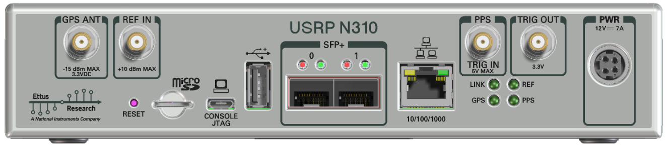
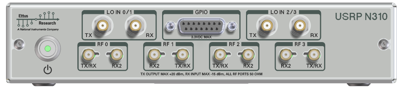
The front panel is used for all RF connections (including the external LO inputs, see External LOs) and all TX/RX connections, as well as the front-panel GPIO.
The connectors labeled RF0 and RF1 are also referred to as slot A, and the connectors labeled RF2 and RF3 are also referred as slot B (matching the internal connections to the daughterboard. Every slot is powered by a single AD9371 RFIC).
When a UHD session is created, an initialization sequence is started. As part of the initialization sequence, the following steps are performed:
This sequence can take a while, depending on the master clock rate and the calibration sequence. To speed things up, the device will retain a state between sessions, but only if no relevant settings were touched. In particular, changing the master clock rate, the clock source, or the calibration masks will force a full re-initialization which is very slow compared to the fast re-initialization. By setting the log level to DEBUG you will be able to observe the exact settings that cause fast vs. slow re-initialization. If you require a full re-initialization every time a UHD session is spawned, specify the force_reinit flag as a device arg. Specifying it will always do the full, slow initialization, but will guarantee a full reset of the RFIC.
To maximally speed up UHD, an initialization sequence is run when the device (or more accurately, the MPM service) starts. This means even on the first run of UHD, the device will already be initialized into a usable state. Note that it will always come up in a default state, which can be changed by modifying the configuration file in /etc/uhd/mpm.conf (see also Configuration Files), such as this:
If you prefer not to have the device initialize on boot, but rather have a fast boot time, add the line skip_boot_init=1 to your /etc/uhd/mpm.conf file.
If there are multiple N3x0 devices in a single UHD session, they will be initialized in parallel. Note that this behaviour can be changed serial initialization by adding serialize_init=1 to the device args (see Device arguments).
The onboard RFIC (AD9371) has built-in calibrations which can be enabled from UHD. A more detailed description of the calibrations can be found in the AD9371 user guide, see chapter "Quadrature Error Correction, Calibration, and ARM configuration".
Not all calibrations available on the AD9371 are applicable to the USRP N310. However, those calibrations that are applicable can be enabled/disabled at initialization time using the tracking_cals and init_cals device args (see also Device arguments). These device can be set to the precise bit mask the chip uses to set those calibrations (e.g., init_cals=0x4DFF,tracking_cals=0xC3) or they can use the following descriptive keys provided by UHD (e.g.init_cals=DEFAULT,tracking_cals=TX_QEC|RX_QEC). The | symbol can be used to combine keys (equivalent to a bitwise OR).
Calibrations can significantly delay the initialization of a session. By only picking relevant calibrations, sessions can be initialized faster.
Key (init_cal) | Function |
|---|---|
| TX_BB_FILTER | Tx baseband filter calibration |
| ADC_TUNER | ADC tuner calibration |
| TIA_3DB_CORNER | Rx TIA filter calibration |
| DC_OFFSET | Rx DC offset calibration |
| TX_ATTENUATION_DELAY | Tx attenuation delay |
| RX_GAIN_DELAY | Rx gain delay calibration |
| FLASH_CAL | ADC flash calibration |
| PATH_DELAY | Path delay calibration |
| TX_LO_LEAKAGE_INTERNAL | Tx LO leakage internal initial calibration |
| TX_LO_LEAKAGE_EXTERNAL | Tx LO leakage external initial calibration (requires external LO) |
| TX_QEC_INIT | Tx QEC initial |
| LOOPBACK_RX_LO_DELAY | Loopback ORx LO delay (ORx not connected by default!) |
| LOOPBACK_RX_RX_QEC_INIT | Loopback Rx QEC initial calibration |
| RX_LO_DELAY | Rx LO delay |
| RX_QEC_INIT | Rx QEC initial calibration |
| BASIC | Preset for minimal calibrations (TX_BB_FILTER, ADC_TUNER, TIA_3DB_CORNER, DC_OFFSET and FLASH_CAL) |
| OFF | Preset for disabling all initial calibrations |
| DEFAULT | Preset for enabling most calibrations (BASIC plus TX_ATTENUATION_DELAY, RX_GAIN_DELAY, PATH_DELAY, RX_QEC_INIT, TX_LO_LEAKAGE_INTERNAL, TX_QEC_INIT, LOOPBACK_RX_LO_DELAY) |
| ALL | Enable all applicable calibrations |
Key (tracking_cal) | Function |
|---|---|
| TRACK_RX1_QEC | Rx1 QEC tracking |
| TRACK_RX2_QEC | Rx2 QEC tracking |
| TRACK_ORX1_QEC | ORx1 QEC tracking |
| TRACK_ORX2_QEC | ORx1 QEC tracking |
| TRACK_TX1_LOL | Tx1 LO leakage tracking |
| TRACK_TX2_LOL | Tx2 LO leakage tracking |
| TRACK_TX1_QEC | Tx1 QEC tracking |
| TRACK_TX2_QEC | Tx2 QEC tracking |
| OFF | Disable all tracking |
| RX_QEC | Enable all RX QEC tracking |
| TX_QEC | Enable all TX QEC tracking |
| TX_LOL | Enable all TX LO leakage tracking |
| DEFAULT | Enable all QEC tracking |
| ALL | Enable all tracking (except ORx) |
The N310 has inputs for external local oscillators. For every daughterboard, there is one input for TX and RX, respectively, resulting in 4 LO inputs total per N310.
Reasons to use an external LO include:
The N310 daughterboard has an EEPROM which is primarily used for storing the serial number, product ID, and other product-specific information. However, it can also be used to store user data, such as calibration information.
Note that EEPROMs have a limited number of write cycles, and storing user data should happen only when necessary. Writes should be kept at a minimum.
Storing data on the EEPROM is done by loading a uhd::eeprom_map_t object into the property tree. On writing this property, the driver code will serialize the map into a binary representation that can be stored on the EEPROM.
The N310 module consists of three PCBs: The motherboard and two daughterboards. Every PCB has a hardware revision number. Modules are always assembled such that the daughterboards have the same revision number. The module revision number is derived from the combination of daughterboard and motherboard hardware revisions. The following table explains which module revision contains which PCB revisions:
| Module Revision | Motherboard Revision | Daughterboard Revision | Minimum UHD Version |
|---|---|---|---|
| A | D | D | 3.11.0.0 |
| B | F | E | 3.12.0.0 |
| C | G | E | 3.13.0.2 |
| D | H | E | 3.14.0.0 |
The module revision is printed on the sticker on the underside of an N310 module chassis, it is contained within the part number. For example, if the sticker says "P/N: 141064A-01L", it is a revision A module.
The following tables describe how FPGA registers are mapped into the PS. This is for reference only, most users will not even have to know about this table.
| AXI Slave | Address Range | UIO Label | Description |
|---|---|---|---|
| Slave 0 | 4000_0000 - 4000_3fff | - | Ethernet DMA SFP0 |
| Slave 1 | 4000_4000 - 4000_4fff | misc-enet-regs0 | Ethernet registers SFP0 |
| Slave 2 | 4000_8000 - 4000_bfff | - | Ethernet DMA SFP1 |
| Slave 3 | 4000_c000 - 4000_cfff | misc-enet-regs1 | Ethernet registers SFP1 |
| Slave 4 | 4001_0000 - 4001_3fff | mboard-regs | Motherboard control |
| Slave 5 | 4001_4000 - 4001_41ff | dboard-regs0 | Daughterboard control, slot A |
| Slave 6 | 4001_8000 - 4001_bfff | dboard-regs1 | Daughterboard control, slot B |
| AXI Slave | Module | Address | Name | Read/Write | Description |
|---|---|---|---|---|---|
| Slave 0 | axi_eth_dma0 | 4000_0000 - 4000_4fff | Ethernet DMA | RW | See Linux Driver |
| Slave 1 | n3xx_mgt_io_core | 4000_4000 | PORT_INFO | RO | SFP port information |
| [31:24] | COMPAT_NUM | RO | - | ||
| [23:18] | 6'h0 | RO | - | ||
| [17] | activity | RO | - | ||
| [16] | link_up | RO | - | ||
| [15:8] | mgt_protocol | RO | 0 - None, 1 - 1G, 2 - XG, 3 - Aurora | ||
| [7:0] | PORTNUM | RO | - | ||
| n3xx_mgt_io_core | 4000_4004 | MAC_CTRL_STATUS | RW | Control 10gE and Aurora mac | |
| [0] | ctrl_tx_enable (PROTOCOL = "10GbE") | RW | - | ||
| [0] | bist_checker_en (PROTOCOL = "Aurora") | RW | - | ||
| [1] | bist_gen_en | RW | - | ||
| [2] | bist_loopback_en | RW | - | ||
| [8:3] | bist_gen_rate | RW | - | ||
| [9] | phy_areset | RW | - | ||
| [10] | mac_clear | RW | - | ||
| n3xx_mgt_io_core | 4000_4008 | PHY_CTRL_STATUS | RW | Phy reset control | |
| n3xx_mgt_io_core | 4000_400C | MAC_LED_CTL | RW | Used by ethtool to indicate port | |
| [1] | identify_enable | RW | - | ||
| [0] | identify_value | RW | - | ||
| mdio_master | 4000_4010 | MDIO_DATA | RW | - | |
| 4000_4014 | MDIO_ADDR | RW | - | ||
| 4000_4018 | MDIO_OP | RW | - | ||
| 4000_401C | MDIO_CTRL_STATUS | RW | - | ||
| n3xx_mgt_io_core | 4000_4020 | AURORA_OVERUNS | RO | - | |
| 4000_4024 | AURORA_CHECKSUM_ERRORS | RO | - | ||
| 4000_4028 | AURORA_BIST_CHECKER_SAMPS | RO | - | ||
| 4000_402C | AURORA_BIST_CHECKER_ERRORS | RO | - | ||
| eth_switch | 4000_5000 | MAC_LSB | RW | Device MAC LSB | |
| 4000_5004 | MAC_MSB | RW | Device MAC MSB | ||
| 4000_6000 | IP | RW | Device IP | ||
| 4000_6004 | PORT1, PORT0 | RW | Device UDP port | ||
| eth_dispatch | 4000_6008 | [1] ndest, [0] bcast | RW | Enable Crossover | |
| 4000_600c | [1] my_icmp_type, [0] my_icmp_code | ||||
| eth_switch | 4000_6010 | BRIDGE_MAC_LSB | Bridge SFP ports in ARM | ||
| 4000_6014 | BRIDGE_MAC_MSB | - | |||
| 4000_6018 | BRIDGE_IP | - | |||
| 4000_601c | BRIDGE_PORT1, BRIDGE_PORT0 | - | |||
| 4000_6020 | BRIDGE_EN | - | |||
| chdr_eth_framer | 4000_6108 onwards | LOCAL_DST_IP | W | Destination IP, MAC, UDP for Outgoing Packet for 256 SIDs | |
| 4000_6208 onwards | LOCAL_DST_UDP_MAC_MSB | W | Destination MAC for outgoing packets (MSB) | ||
| 4000_6308 onwards | LOCAL_DST_MAC_LSB | W | Destination MAC for outgoing packets (LSB) | ||
| 4000_7000 onwards | REMOTE_DST_IP | W | Destination IP, MAC, UDP for Outgoing Packet for 16 local addrs | ||
| 4000_7400 onwards | REMOTE_DST_UDP_MAC_HI | W | Destination MAC (MSB) | ||
| 4000_7800 onwards | REMOTE_DST_MAC_LO | W | Destination MAC (LSB) | ||
| Slave 2 | axi_eth_dma1 | 4000_8000 | - | Same as Slave 0, different base address | |
| Slave 3 | n3xx_mgt_io_core | 4000_c001 - 4000_cfff | - | - | Same as Slave 1, different base address |
| eth_dispatch | 4000_d000 - 4000_dfff | - | - | Same as Slave 1, different base address | |
| eth_switch | 4000_e000 - 4000_efff | - | - | Same as Slave 1, different base address | |
| Slave 4 | n3xx_core | 4001_0000 | COMPAT_NUM | R | FPGA Compat Number |
| [31:16] | Major | RO | - | ||
| [15:0] | Minor | RO | - | ||
| 4001_0004 | DATESTAMP | RO | - | ||
| 4001_0008 | GIT_HASH | RO | - | ||
| 4001_000C | SCRATCH | RO | - | ||
| 4001_0010 | REG_DEVICE_ID | RW | RFNoC Device ID | ||
| 4001_0014 | REG_RFNOC_INFO | RO | RFNoC Information | ||
| [31:16] | CHDR_W | RO | RFNoC CHDR Width in Bits | ||
| [15:0] | RFNOC_PROTOVER | RO | RFNoC Protocol Version | ||
| 4001_0018 | CLOCK_CTRL | ||||
| [0] | pps select (internal 10 MHz) | RW | One-hot encoded pps_select to use the external PPS input. | ||
| [1] | pps select (internal 25 MHz) | RW | One-hot encoded pps_select to use the internally generated PPS with a 10 MHz ref_clk. | ||
| [2] | pps select (external) | RW | One-hot encoded pps_select to use the internally generated PPS with a 25 MHz ref_clk. | ||
| [3] | pps select (GPSDO) | RW | One-hot encoded pps_select to use the PPS from the GPSDO input to the FPGA. | ||
| [4] | pps output enable | RW | |||
| [8] | ref clk mmcm reset | WO | - | ||
| [9] | ref clk mmcm locked | RO | - | ||
| [12] | meas clk mmcm reset | WO | - | ||
| [13] | meas clk mmcm locked | RO | - | ||
| 4001_001C | XADC_READBACK | RO | - | ||
| [11:0] | FPGA temperature | RO | |||
| 4001_0020 | BUS_CLK_RATE | RO | - | ||
| 4001_0024 | BUS_CLK_COUNT | RO | - | ||
| 4001_0028 | SFP_PORT0_INFO | RO | - | ||
| 4001_002C | SFP_PORT1_INFO | RO | - | ||
| 4001_0030 | FP_GPIO_MASTER | RO | GPIO master select bits. One bit per GPIO. LSB is for GPIO 0. Set bit to 0 for Radio, 1 for PS. | ||
| 4001_0034 | FP_GPIO_RADIO_SRC | RO | Radio channel source select bits. Two bits per GPIO. Bits [1:0] are for GPIO 0. Set to 00 for channel 0, 01 for channel 1, etc. | ||
| 4001_0048 | NUM_TIMEKEEPERS | RO | Number of radio timekeepers | ||
| n3xx_mgt_io_core (NPIO0) | 4001_0200 | PORT_INFO | RO | ||
| 4001_0204 | MAC_CTRL_STATUS | RW | |||
| 4001_0208 | PHY_CTRL_STATUS | RW | |||
| 4001_0220 | AURORA_OVERUNS | RO | |||
| 4001_0224 | AURORA_CHECKSUM_ERRORS | RO | |||
| 4001_0228 | AURORA_BIST_CHECKER_SAMPS | RO | |||
| 4001_022c | AURORA_BIST_CHECKER_ERRORS | RO | |||
| n3xx_mgt_io_core (NPIO1) | 4001_0240 | PORT_INFO | RO | ||
| 4001_0244 | MAC_CTRL_STATUS | RW | |||
| 4001_0248 | PHY_CTRL_STATUS | RW | |||
| 4001_0260 | AURORA_OVERUNS | RO | |||
| 4001_0264 | AURORA_CHECKSUM_ERRORS | RO | |||
| 4001_0268 | AURORA_BIST_CHECKER_SAMPS | RO | |||
| 4001_026c | AURORA_BIST_CHECKER_ERRORS | RO | |||
| n3xx_mgt_io_core (QSFP0) | 4001_0280 | PORT_INFO | RO | ||
| 4001_0284 | MAC_CTRL_STATUS | RW | |||
| 4001_0288 | PHY_CTRL_STATUS | RW | |||
| 4001_02a0 | AURORA_OVERUNS | RO | |||
| 4001_02a4 | AURORA_CHECKSUM_ERRORS | RO | |||
| 4001_02a8 | AURORA_BIST_CHECKER_SAMPS | RO | |||
| 4001_02ac | AURORA_BIST_CHECKER_ERRORS | RO | |||
| n3xx_mgt_io_core (QSFP1) | 4001_02c0 | PORT_INFO | RO | ||
| 4001_02c4 | MAC_CTRL_STATUS | RW | |||
| 4001_02c8 | PHY_CTRL_STATUS | RW | |||
| 4001_02e0 | AURORA_OVERUNS | RO | |||
| 4001_02e4 | AURORA_CHECKSUM_ERRORS | RO | |||
| 4001_02e8 | AURORA_BIST_CHECKER_SAMPS | RO | |||
| 4001_02ec | AURORA_BIST_CHECKER_ERRORS | RO | |||
| n3xx_mgt_io_core (QSFP2) | 4001_0300 | PORT_INFO | RO | ||
| 4001_0304 | MAC_CTRL_STATUS | RW | |||
| 4001_0308 | PHY_CTRL_STATUS | RW | |||
| 4001_0320 | AURORA_OVERUNS | RO | |||
| 4001_0324 | AURORA_CHECKSUM_ERRORS | RO | |||
| 4001_0328 | AURORA_BIST_CHECKER_SAMPS | RO | |||
| 4001_032c | AURORA_BIST_CHECKER_ERRORS | RO | |||
| n3xx_mgt_io_core (QSFP3) | 4001_0340 | PORT_INFO | RO | ||
| 4001_0344 | MAC_CTRL_STATUS | RW | |||
| 4001_0348 | PHY_CTRL_STATUS | RW | |||
| 4001_0360 | AURORA_OVERUNS | RO | |||
| 4001_0364 | AURORA_CHECKSUM_ERRORS | RO | |||
| 4001_0368 | AURORA_BIST_CHECKER_SAMPS | RO | |||
| 4001_036C | AURORA_BIST_CHECKER_ERRORS | RO | |||
| Slave 5 | 4001_4000 | 4001_41FF | Clocking | see Clocking regmap | |
| 4001_4200 | 4001_43FF | Sync | see Sync regmap | ||
| 4001_4400 | 4001_45FF | open | open | open | |
| 4001_4600 | 4001_47FF | Daughterboard | see Daughterboard regmap (EISCAT) | ||
| 4001_6000 | 4001_6FFF | JESD Core 0 | see JESD regmap (EISCAT) | ||
| 4001_7000 | 4001_7FFF | JESD Core 1 | see JESD regmap (EISCAT) | ||
| Slave 6 | 4001_8000 - 4001_bfff | see above | - | same as Slave 5 |
EEPROM flags can be set with
$ eeprom-set-flags 0xFLAGS
where FLAGS is the hex number that you can construct with the following table of bits:
| Bit | Description |
|---|---|
| 0 | Auto-boot (1=on) |
| 2 | TPM (0=present) |
For example, to set your device to auto-boot, with TPM, the flag value is 0x1, so
$ eeprom-set-flags 0x1
The N310 supports four gain profiles: default, manual, default_rf_filter_bypass_always_on, and default_rf_filter_bypass_always_off.
Usually, UHD will program individual gain components to create an overall gain that is selected. The N310 daughterboards have three gain stages per path (two digital step attenuators (DSAs), and one amplifier). When using the manual profile, the DSAs and amplifiers can be programmed directly. In the other gain profiles, a single, overall gain can be given, and UHD will attempt to program the gain stages based on hard-coded gain tables. The difference between the three "default" profiles is how the amplifier is used: Either it is always on, always off, or it is switched on and off to optimize linearity.
Note: This is a highly advanced feature. Most users will not have to use this!
The N310 daughterboard splits the TX and RX paths into 4 and 7 different bands, respectively, to hardware-optimize the RF fidelity at all available frequencies.
See the schematics for more details.
Using the rx_band_map and tx_band_map device args, it is possible to move the band edges in software. This may be useful if the hardware was modified to use different filters, for example, because a signal of interest always falls onto a band edge. Using the tx_band_map or rx_band_map device arguments, you can provide a list of lower band edges for every band. Make sure to provide 4 (for Tx) or 7 (for Rx) floating-point values. The first value should always be zero (0.0). It may make sense to encode these values in your uhd.conf file:
The N300/N310 utilize the Analog Devices AD9371 AFE which contain programmable FIR filters in both the transmit and receive paths for each of the RF channels. These filters are available using the Digital Filter API in UHD.
| Filter Name | AD9371 Channel | Max Taps |
|---|---|---|
| RX1_FIR | 1 | 48 |
| RX2_FIR | 2 | 48 |
| RX1RX2_FIR | 1 and 2 | 48 |
| TX1_FIR | 1 | 32 |
| TX2_FIR | 2 | 32 |
| TX1TX2_FIR | 1 and 2 | 32 |
Each filter is applied at 2x the master_clock_rate, or 250 MHz by default.
The Filter API also allows to set some 3 dB analog filters on the AD9371 through the set_tx_bandwidth and set_rx_bandwidth UHD functions.
This is a small example on how to set the TX FIR and TX bandwidth.
Like the USRP X300 series, the N320/N321 has connectors on both the front and back panel. The back panel holds the power connector, all network connections, USB connections for serial console (see Serial connection), JTAG, peripherals, SMA connectors for GPS antenna input, 10 MHz clock reference, PPS time reference input and output (TRIG in/out), the slot for the SD card (see also The SD card), and indicator LEDs.
The following indicator LEDs are used:
The rear panel is identical between the N320 and the N321 with the exception of the product name above the SFP+ connectors.
The front panel is used for all RF connections (including the external LO inputs, see External LOs) and all TX/RX connections, as well as the front-panel GPIO (N320 only!).
The connectors labeled RF0 are also referred to as slot A, and the connectors labeled RF1 are also referred as slot B (matching the internal connections to the daughterboard).
When a UHD session is created, an initialization sequence is started. As part of the initialization sequence, the following steps are performed:
This sequence can take a while, depending on the master clock rate and the calibration sequence. To speed things up, the device will retain a state between sessions, but only if no relevant settings were touched. In particular, changing the master clock rate or the clock source will force a full re-initialization which is slower compared to the fast re-initialization. By setting the log level to DEBUG you will be able to observe the exact settings that cause fast vs. slow re-initialization. If you require a full re-initialization every time a UHD session is spawned, specify the force_reinit flag as a device arg. Specifying it will always do the full, slow initialization, but will guarantee a full reset digital chains.
To maximally speed up UHD, an initialization sequence is run when the device (or more accurately, the MPM service) starts. This means even on the first run of UHD, the device will already be initialized into a usable state. Note that it will always come up in a default state, which can be changed by modifying the configuration file in /etc/uhd/mpm.conf (see also Configuration Files), such as this:
If you prefer not to have the device initialize on boot, but rather have a fast boot time, add the line skip_boot_init=1 to your /etc/uhd/mpm.conf file.
The N320/N321 can perform some simple calibration for I/Q imbalance and DC offset, the same way as the X300 series. Refer to Device Calibration and Frontend Correction for more details.
The N320/N321 can utilize an external LO that is connected to the front panel connectors. For the N320, the LO IN TX and LO IN RX connectors are used. For the N321, the RX LO IN1 and TX LO IN1 connectors are used. One or both daughterboards may use this external LO signal by setting the channel's LO source to "external". When the source is set to "external", reading the LO frequency will return the ideal frequency for an external LO source.
The nominal LO input level is +5 dBm. Actual LO input levels should be within +/- 2 dB of that value (i.e., between +3 dBm and +7 dBm).
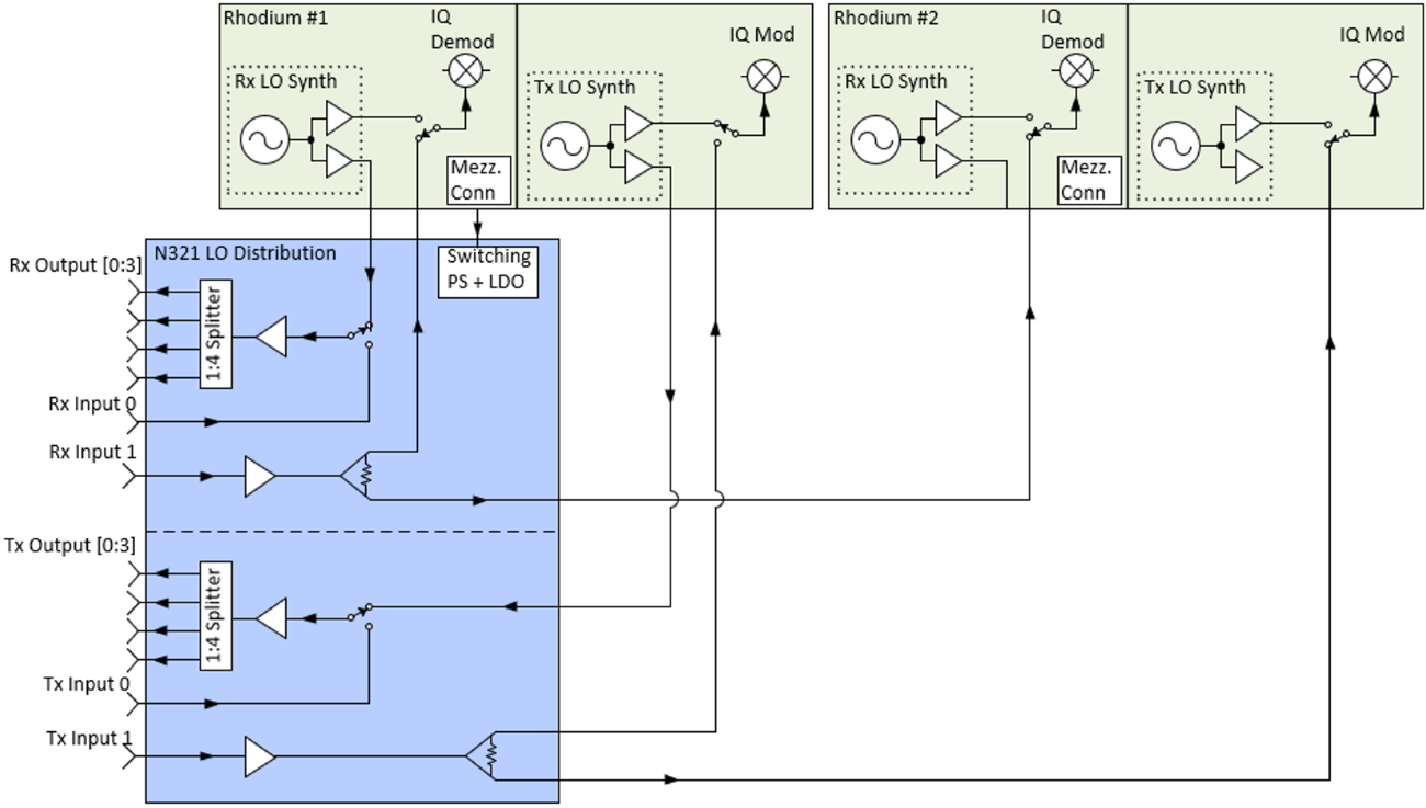
The N321 has an additional board to perform LO signal splitting and distribution. The 4 output ports, OUT0 through OUT3, are driven by a 1:4 splitter which can be sourced from the corresponding IN0 front panel port or the LO on the daughterboard in slot A. To use the IN0 front panel port, set LO export enabled to false. To use the LO located on the daughterboard in slot A, set LO export enabled to true.
Each of the 4 output ports, OUT0 through OUT3, have an internal terminator which must be disabled before use. These can be controlled through the RFNoC radio block's API, the property tree, or directly through commands in the MPM shell.
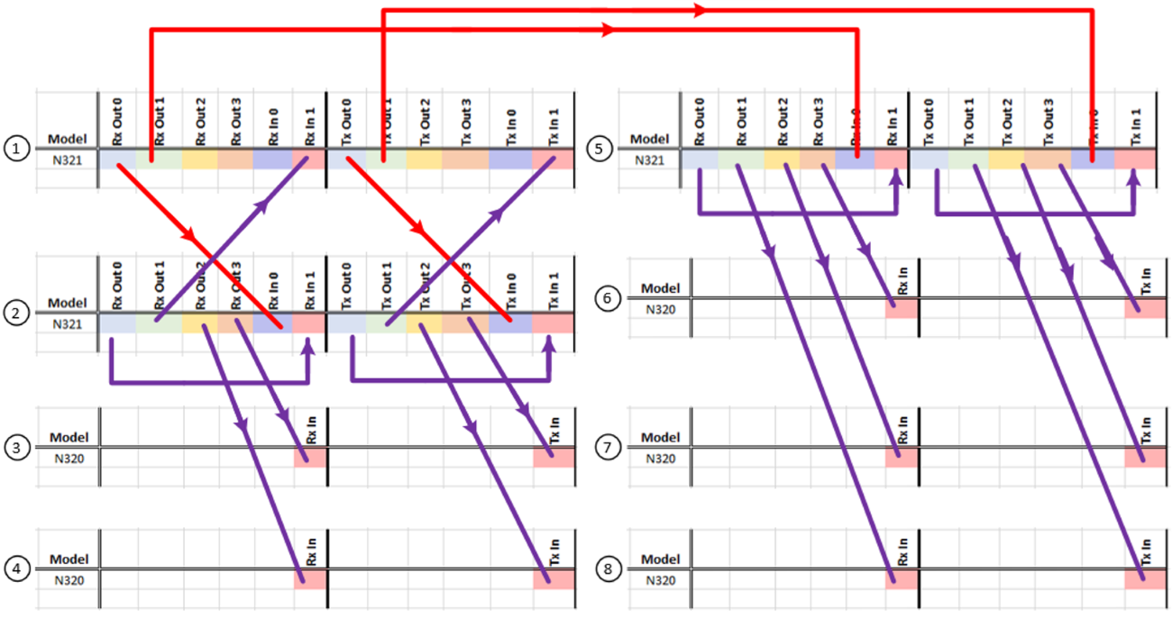
By using matched length cabling with N321s, up to 16 modules can use both of their RX and TX channels while sharing a single N321's LO signal, resulting in a 32 by 32 channel single shared LO configuration. This 32 by 32 channel configuration can also utilize an external LO signal, allowing an already split external LO signal to support larger configurations of 64 by 64 channels, 128 by 128 channels, and larger.
The following diagram shows the connections necessary to create a 16 by 16 channel configuration with a single shared LO source.
The protocols supported on the SFP+ and QSFP+ ports depend on the FPGA image currently loaded.
| Interface | HG | XG | WX | XQ | AQ |
|---|---|---|---|---|---|
| SFP+ 0 | 1 GbE | 10 GbE | White Rabbit | White Rabbit | 10 GbE |
| SFP+ 1 | 10 GbE | 10 GbE | 10 GbE | Unused | 10 GbE |
| QSFP+ lane 0 | Unused | Unused | Unused | 10 GbE | Aurora |
| QSFP+ lane 1 | Unused | Unused | Unused | 10 GbE | Aurora |
| QSFP+ lane 2 | Unused | Unused | Unused | Unused | Aurora |
| QSFP+ lane 3 | Unused | Unused | Unused | Unused | Aurora |
In an unmodified FPGA image, N320/N321 perform several steps of digital signal processing between the RFNoC Radio block and the ADC/DAC.
It should be noted that the DACs/ADCs run at twice the master clock rate (e.g., if the master clock rate is 250 MHz, the DACs/ADCs are clocked at 500 MHz). We perform a sample rate conversion to the master clock rate within the FPGA.
The IQ and DC offset compensation components can be controlled from the host side using the correction APIs. The following snippet shows the control of these APIs from the host side using the multi_usrp APIs:
When using the RFNoC API, use the uhd::rfnoc::radio_control API calls with the same names.
Notes:
The halfband decimators/interpolators are not configurable. They are 47-tap halfband filters with the following coefficients:
-62, 0, 194, 0, -440, 0, 855, 0, -1505, 0, 2478, 0, -3900, 0, 5990, 0, -9187, 0, 14632, 0, -26536, 0, 83009, 131071, 83009, 0, -26536, 0, 14632, 0, -9187, 0, 5990, 0, -3900, 0, 2478, 0, -1505, 0, 855, 0, -440, 0 194, 0, -62.
EEPROM flags can be set with
$ eeprom-set-flags 0xFLAGS
where FLAGS is the hex number that you can construct with the following table of bits:
| Bit | Description |
|---|---|
| 0 | Auto-boot (1=on) |
| 2 | TPM (0=present) |
For example, to set your device to auto-boot, with TPM, the flag value is 0x1, so
$ eeprom-set-flags 0x1