|
USRP Hardware Driver and USRP Manual
Version: 003.008.000-0-gfd61f0cc
UHD and USRP Manual
|


|
|
USRP Hardware Driver and USRP Manual
Version: 003.008.000-0-gfd61f0cc
UHD and USRP Manual
|
|
This will run you through the first steps relevant to get your USRP E300/310 up and running.
There are two different methods to connect to the device
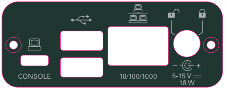
For the first boot, booting with the serial cable connected to the device is recommended, as it allows to review and modify the network configuration, and allows to enter the bootloader in case of issues during the boot.
To use the serial connection together with a Linux or OSX machine (most other UNIX variants come with a version of screen, too) a terminal emulator such as screen can be used:
$ sudo screen /dev/ttyUSB0 115200
The exact device node /dev/ttyUSB0 depends on your operating system's driver and other USB devices that might be already connected. It can be usually found by perusing the output of dmesg or journalctl, after connecting the USRP E300/E310 device to your host computer.
An example of a dmesg output for the serial to usb converter:
924.102764] usb 1-1: FTDI USB Serial Device converter now attached to ttyUSB0
On Microsoft Windows the serial connection can be established using a tool such as Putty by selecting a baudrate of 115200 and the corresponding serial port for the serial to usb converter.
In both cases you should see boot messages fly by and finally end up with a login prompt similar to the following:
ettus-e300 login:
Note: The username is 'root' and the default password is empty.
You should be presented with a shell similar to the following
root@ettus-e300:~#
The USRP E300/E310 device relies on the DHCP protocol to automatically obtain an IP address. In case your network setup does not include a DHCP server, refer to the section Serial connection or configure a DHCP server to hand out IP addresses on your network.
After the device obtained an IP address you can log in from a Linux or OSX machine by typing:
$ ssh [email protected]
where the IP address depends on your local network setup.
On Microsoft Windows again the connection can be established using a tool such as Putty, by selecting a username of root without password.
You should be presented with a shell similar to the following
root@ettus-e300:~#
In order to facilitate software development for the integrated ARM Cortex-A9 processor, a Yocto Project based SDK is provided in the download section of our website. This SDK contains a cross-compiler, a cross-linker as well as a cross-debugger and can be used to develop your user space applications for the Ettus USRP-E300/E310 devices.
The following section will guide you through the installation of the provided SDK on a Linux development machine.
It is necessary for the SDK version and the image version to match, to ensure the versions of the software installed on the device and the version of the software the SDK will build against match.
If you are not sure which image is installed on your device, upgrading to the latest stable version is recommended. See the appropriate section for details on upgrading.
To install the toolchain you downloaded type:
$ ./oecore-${TCLIBC}-${SDK_ARCH}-${IMAGE_BASENAME}-${TUNE_PKGARCH}.sh
This will prompt you for an installation path. Please ensure you have sufficient disk space, as each of the SDKs may require several gigabytes of disk space (depends on the image flavor selected).
This will allow you to compile UHD as well as (depending on the image flavor) other software.
Please note, that while several toolchains can be installed in parallel, they have to be installed to different directories.
Having installed the toolchain in the last step, in order to build software for your device open a new shell and type:
$ . <yoursdkinstallpath>/environment-setup-armv7ahf-vfp-neon-oe-linux-gnueabi
This will modifiy the PATH, CC, CXX etc, environment variables and allow you to compile software for your USRP E300/E310 device. To verify all went well you can try:
$ $CC -dumpmachine
which should return 'arm-oe-linux-gnueabi'.
 $ cmake -DCMAKE_TOOLCHAIN_FILE=<youruhdsrc>/host/cmake/Toolchains/oe-sdk_cross.cmake -DENABLE_E300 ..
 $ make
Several GNU Radio components depend on running binaries built for the build machine during compile. These binaries can be built and used for cross compiling, but this is an advanced topic.
The file system images are built using OpenEmbedded Core. The repo tool is used to manage the versions of the various layers that supply recipes for building the image. For more documentation see http://www.yoctoproject.org. These notes will show you how to rebuild the files used to create the SD card included with the E310. These instructions assume you ahve a working knowledge of Linux.
repo. At this point you should review the file in conf/local.conf and make sure path names make sense for your machine.
When this completes, the files needed to create the sd card are in tmp-glibc/deploy/images/ettus-e300
The sdk is in tmp-glibc/deploy/sdk
Note that you can set the MACHINE variable in `local.conf so that you no longer need to set it from the command line.
When you log back in, you will need to setup the OpenEmbedded environment again by:
UHD software will automatically select the USRP E300/E310 images from the installed images package. The image selection can be overridden with the fpga device address parameter.
Example device address string representations to specify non-standard image:
$ uhd_usrp_probe --args='fpga=usrp_e310_fpga.bit'
The USRP-E Series device features an on-board JTAG connector (see Debugging custom FPGA designs with Xilinx Chipscope) that can be accessed on the PCB of the device. The iMPACT tool in the Xilinx Programming Tools (ISE, iMPACT) package can be used to load an image over the JTAG interface.
If you have iMPACT installed, you can use the impact_jtag_programmer.sh tool to install images. Make sure your e3x0 is powered on and connected to your computer using the internal JTAG connector. Then run the tool:
<path_to_uhd_tools>/impact_jtag_programmer.sh --fpga-path=<fpga_image_path>
You may need to change the USRP's IP address for several reasons:
Using a PPS signal for timestamp synchronization requires a square wave signal with the following a 5Vpp amplitude.
To test the PPS input, you can use the following tool from the UHD examples:
<args> are device address arguments (optional if only one USRP device is on your machine)
cd <install-path>/lib/uhd/examples ./test_pps_input –args=<args>
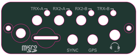
Your USRP-E Series device comes with an internal GPSDO. In order to get a lock on a satellite an external GPS antenna is required.
The device provides a 3.3V supply voltage to an external antenna connected to the GPS port of your device. Note that this supply voltage is turned off in order to safe power upon destruction of the software object.
Please see the E3x0/X3x0 GPIO API for information on configuring and using the GPIO bus.
Xilinx chipscope allows for debugging custom FPGA designs similar to a logic analyzer. USRP-E series devices can be used with Xilinx chipscope using the internal JTAG connector.
Further information on how to use Chipscope can be found in the Xilinx Chipscope Pro Software and Cores User Guide (UG029).
The USRP E310 MIMO XCVR daughterboard features an integrated MIMO capable RF frontend.
The RF frontend has individually tunable receive and transmit chains. Both transmit and receive can be used in a MIMO configuration. For the MIMO case, both receive frontends share the RX LO, and both transmit frontends share the TX LO. Each LO is tunable between 50 MHz and 6 GHz.
All frontends have individual analog gain controls. The receive frontends have 73 dB of available gain; and the transmit frontends have 89.5 dB of available gain. Gain settings are application specific, but it is recommended that users consider using at least half of the available gain to get reasonable dynamic range.
The frontends provide a lo-locked sensor that can be queried through the UHD API.
There are two complete DDC and DUC DSP chains in the FPGA. In the single channel case, only one chain is ever used. To receive / transmit from both channels, the user must set the RX or TX subdevice specification.
In the following example, a E310 MIMO XCVR is installed. Channel 0 is sourced from subdevice A, and channel 1 is sourced from subdevice B
The following sensors are available for the USRP-E Series motherboards; they can be queried through the API.
Your USRP-E series device can be used in network mode for narrow band signal observation, evaluation and debugging purposes.
Please note that when compared with normal operation as a standalone device the usable bandwidth is limited and therefore Network Mode is not the recommended mode of operation.
In order to use the device in network mode it is necessary to start the usrp_e3x0_network_mode executable on the device. In order to start the executable please log into your device either via SSH or serial console(see First boot) and type
$ usrp_e3x0_network_mode
Your device should now be discoverable by your host computer via the usual UHD tools. If you are having trouble communicating with your device see the Communication Problems section.
In a single-device configuration, the USRP device must have a unique IPv4 address on the host computer. The USRP can be identified through its IPv4 address or resolvable hostname. See the application notes on Device Identification. Use this addressing scheme with the uhd::usrp::multi_usrp interface (not a typo!).
Example device address string representation for a USRP-E Series device with IPv4 address 192.168.10.2:
addr=192.168.10.2
In a multi-device configuration, each USRP device must have a unique IPv4 address on the host computer. The device address parameter keys must be suffixed with the device index. Each parameter key should be of the format <key><index>. Use this addressing scheme with the uhd::usrp::multi_usrp interface.
Example device address string representation for 2 USRPs with IPv4 addresses 192.168.10.2 and 192.168.20.2:
addr0=192.168.10.2, addr1=192.168.20.2
When setting up a development machine for the first time, you may have various difficulties communicating with the USRP device. The following tips are designed to help narrow down and diagnose the problem.
This is a common error that occurs when you have set the subnet of your network interface to a different subnet than the network interface of the USRP device. For example, if your network interface is set to 192.168.20.1, and the USRP device is 192.168.10.2 (note the difference in the third numbers of the IP addresses), you will likely see a 'no control response' error message.
Fixing this is simple - just set the your host PC's IP address to the same subnet as that of your USRP device. Instructions for setting your IP address are in the previous section of this documentation.
When the IP address is not specified, the device discovery broadcasts UDP packets from each Ethernet interface. Many firewalls will block the replies to these broadcast packets. If disabling your system's firewall or specifying the IP address yields a discovered device, then your firewall may be blocking replies to UDP broadcast packets. If this is the case, we recommend that you disable the firewall or create a rule to allow all incoming packets with UDP source port 49152.
The USRP device will reply to ICMP echo requests ("ping"). A successful ping response means that the device has booted properly and that it is using the expected IP address.
ping 192.168.10.2
Use Wireshark to monitor packets sent to and received from the device.
When there is network traffic arriving at the Ethernet port, LEDs will light up. You can use this to make sure the network connection is correctly set up, e.g. by pinging the USRP and making sure the LEDs start to blink.
/etc/ssh/sshd_config, unmcomment the line #X11Forwarding no and change "no" to "yes".OpenBTS allows the USRP E300/E310 to serve as a GSM base station capable of providing voice and messaging services to standard GSM handsets. General information on the OpenBTS project can be found at the official webpage.
Special instructions to install OpenBTS on the E300/E310 can be found on the OpenBTS wiki.
 1.8.13