|
USRP Hardware Driver and USRP Manual
Version: 003.009.004-0-g2b5a88bb
UHD and USRP Manual
|


|
|
USRP Hardware Driver and USRP Manual
Version: 003.009.004-0-g2b5a88bb
UHD and USRP Manual
|
|
This will run you through the first steps relevant to get your USRP E310 up and running.
There are two different methods to connect to the device
For the first boot, booting with the serial cable connected to the device is recommended, as it allows to review and modify the Network configuration and allows to enter the bootloader in case of issues during the boot.
To use the serial connection together with a Linux or OSX machine (most other UNIX variants come with a version of screen, too) a terminal emulator such as screen can be used:
$ sudo screen /dev/ttyUSB0 115200
The exact device node /dev/ttyUSB0 depends on your operating system's driver and other USB devices that might be already connected. It can be usually found by perusing the output of dmesg or journalctl, after connecting the USRP E310 device to your host computer.
An example of a dmesg output for the serial to usb converter:
924.102764] usb 1-1: FTDI USB Serial Device converter now attached to ttyUSB0
On Microsoft Windows the serial connection can be established using a tool such as Putty by selecting a baudrate of 115200 and the corresponding serial port for the serial to usb converter.
In both cases you should see boot messages fly by and finally end up with a login prompt similar to the following:
ettus-e300 login:
Note: The username is 'root' and the default password is empty.
You should be presented with a shell similar to the following
root@ettus-e300:~#
The USRP E310 device relies on the DHCP protocol to automatically obtain an IP address. In case your network setup does not include a DHCP server, refer to the section Serial connection or configure a DHCP server to hand out IP addresses on your network.
After the device obtained an IP address you can log in from a Linux or OSX machine by typing:
$ ssh [email protected]
where the IP address depends on your local network setup.
On Microsoft Windows again the connection can be established using a tool such as Putty, by selecting a username of root without password.
You should be presented with a shell similar to the following
root@ettus-e300:~#
In order to facilitate software development for the integrated ARM Cortex-A9 processor, a Yocto Project based SDK is provided in the download section of our website. This SDK contains a cross-compiler, a cross-linker as well as a cross-debugger and can be used to develop your user space applications for the Ettus USRP-E310 devices.
The following section will guide you through the installation of the provided SDK on a Linux development machine.
It is necessary for the SDK version and the image version to match, to ensure the versions of the software installed on the device and the version of the software the SDK will build against match.
If you are not sure which image is installed on your device, upgrading to the latest stable version is recommended. See the appropriate section for details on upgrading.
To install the toolchain you downloaded type:
$ ./oecore-x86_64-armv7ahf-vfp-neon-toolchain-nodistro.0.sh
This will prompt you for an installation path. Please ensure you have sufficient disk space, as each of the SDKs may require several gigabytes of disk space (depends on the image flavor selected).
This will allow you to compile UHD as well as (depending on the image flavor) other software.
Please note, that while several toolchains can be installed in parallel, they have to be installed to different directories.
Having installed the toolchain in the last step, in order to build software for your device open a new shell and type:
$ . <yoursdkinstallpath>/environment-setup-armv7ahf-vfp-neon-oe-linux-gnueabi
This will modifiy the PATH, CC, CXX etc, environment variables and allow you to compile software for your USRP E310 device. To verify all went well you can try:
$ $CC -dumpmachine
which should return 'arm-oe-linux-gnueabi'.
The E310 comes with UHD already installed on the SD card. You will only need to build UHD and install it if there is a critical bug fix in a later UHD or you have custom UHD modifications.
 $ cmake -DCMAKE_TOOLCHAIN_FILE=../host/cmake/Toolchains/oe-sdk_cross.cmake -DCMAKE_INSTALL_PREFIX=/usr -DENABLE_E300=ON ..
 $ make
For instructions on building UHD on a PC to interact with your E-Series device, follow these instructions: Building UHD
GNU Radio is already installed on the SD card. You only need to build GNU Radio for the E3XX if you are doing custom GNU Radio development work.
Several GNU Radio components depend on running binaries built for the build machine during compile. These binaries can be built and used for cross compiling, but this is an advanced topic.
The file system images are built using OpenEmbedded Core. The repo tool is used to manage the versions of the various layers that supply recipes for building the image. For more documentation see http://www.yoctoproject.org. These notes will show you how to rebuild the files used to create the SD card included with the E310. These instructions assume you have a working knowledge of Linux.
Once you have rebuilt the factory image, you can create your own custom recipes to build file system images for specific application.
repo. When this completes, the files needed to create the SD card are in tmp-glibc/deploy/images/ettus-e300. Building the file that is written directly to the SD card is covered later in this document.
tmp-glibc/deploy/sdk Note that you can set the MACHINE variable in `local.conf so that you no longer need to set it from the command line.There is a script in the meta-ettus BSP layer that builds SD card images for all E3XX series devices and the sdk.
From the build directory run:
When the script finishes, the SD ard image files are in ./images and the sdk is in tmp-glibc/deploy/sdk/ .
In order to upgrade or reinitialize a sd card for the first time, you can use the 'dd' tool. Make sure that you are using the right block device for your sd card as failing to do so can wipe your harddrive.
Replace <yourimage>.direct with your image file name and yoursdcard with your blockdevice e.g. /dev/mmcblk0 or /dev/sdb.
$ sudo dd if=<yourimage>.direct of=/dev/<yoursdcard> bs=1M
Notes: The commands will wipe the entire sd card and reinitialize it. Newer images need a 8GB sd card.
UHD software will automatically select the USRP E310 images from the installed images package. The image selection can be overridden with the fpga device address parameter.
Example device address string representations to specify non-standard image:
$ uhd_usrp_probe --args='fpga=usrp_e310_fpga.bit'
The USRP-E Series device features an on-board JTAG connector (see Debugging custom FPGA designs with Xilinx Chipscope) that can be accessed on the PCB of the device. The iMPACT tool in the Xilinx Programming Tools (ISE, iMPACT) package can be used to load an image over the JTAG interface.
If you have iMPACT installed, you can use the impact_jtag_programmer.sh tool to install images. Make sure your e3x0 is powered on and connected to your computer using the internal JTAG connector. Then run the tool:
<path_to_uhd_tools>/impact_jtag_programmer.sh --fpga-path=<fpga_image_path>
You may need to change the USRP's IP address for several reasons:
For examples refer to the Network configuration section.
The status LED in the power switch indicates the power and charge status. It's behavior is firmware version dependent.
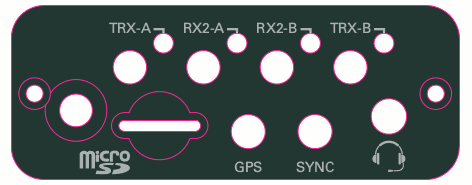
Unlike most USRP devices, the E310 does not have independent reference clock and time source inputs. It is possible, however, to discipline the internal reference clock using an external time (PPS) source connected to the SYNC input pin. The E310 FPGA has a subsystem that can use the PPS signal from the SYNC pin or the internal GPS to align edges of the reference clock to edges of a shared PPS signal. This alignment happens automatically when the time source in UHD is set to "gpsdo" or "external". Please note that because the SYNC input can only accept a PPS signal, the only supported value for the reference clock source is "internal".
Using a PPS signal for timestamp synchronization requires a LVCMOS or a 5V logic input signal. An external PPS can be used to discipline the internal reference clock. This feature is automatically enabled with the time source is set to "external".
To test the PPS input, you can use the following tool from the UHD examples:
<args> are device address arguments (optional if only one USRP device is on your machine)
cd <install-path>/lib/uhd/examples ./test_pps_input –args=<args>
Your USRP-E Series device comes with an internal GPS. In order to get a lock on a satellite an external GPS antenna is required. The PPS from the internal GPS can be used to discipline the internal reference clock. This feature is automatically enabled with the time source is set to "gpsdo".
The device provides a 3.3V supply voltage to an external antenna connected to the GPS port of your device. Note that this supply voltage is turned off in order to safe power upon destruction of the software object.
Your USRP-E Series device has an onboard IMU that provides 9 axis (Gyro, Accelerometer and compass) functionality.
The USRP-E Series images ship with several example applications based on RTIMULib that allow the user to explore the basic functionality of the IMU as well as to calibrate it.
To test the accelerometer, run:
$ RTIMULibDrive
This will print the current acclerometer values on the console.
To launch the IMU calibration procedure, run:
$ RTIMULibCal
and follow the onscreen instructions. Please note that magnetometer calibration is important to obtain sensible results if the IMU is to be used in sensor fusion applications.
Using X11 forwarding over SSH (see Frequently Asked Questions) a complete sensor fusion application can be run over SSH from a host computer by typing:
$ RTIMULibDemo
This should open a graphical window on the host computer that displays the various outputs of the IMU, as well as quaternion measurements based on different sensor fusion algorithms.
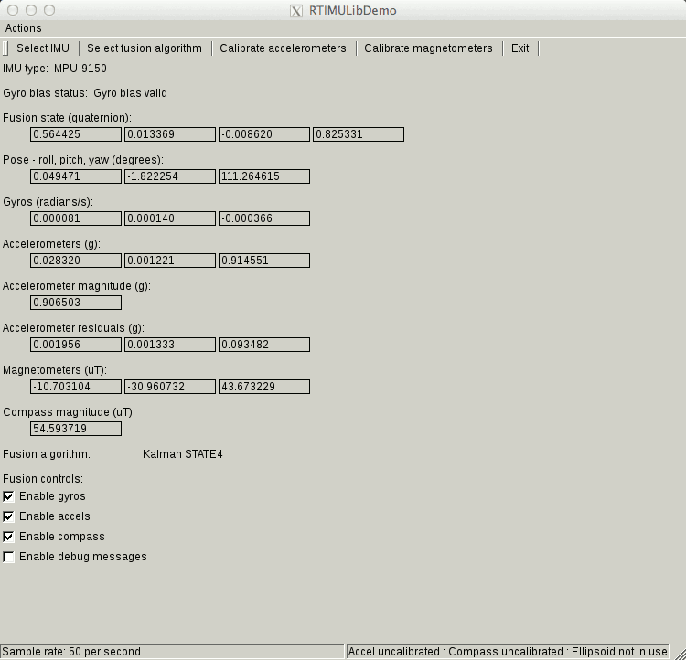
For more advanced IMU based applications please refer to the RTIMULib repository as well as the datasheets.
Please see the E3x0/X3x0 GPIO API for information on configuring and using the GPIO bus.
The E3x0 2.5 mm Audio Jack TRRS pins are assigned as follows: Tip=Mic, Ring1=Right, Ring2=Left, Sleeve=GND.
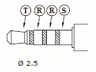
The Left/Right audio outputs are compatible with typical low-impedance headphones (16 to 32 Ohms). The Microphone pin provides approximately 2 mA bias at 2.2 V when not suspended. A variety of pin configurations can be found on commonly available headsets, so an adapter may be required.
Xilinx chipscope allows for debugging custom FPGA designs similar to a logic analyzer. USRP-E series devices can be used with Xilinx chipscope using the internal JTAG connector.
Further information on how to use Chipscope can be found in the Xilinx Chipscope Pro Software and Cores User Guide (UG029).
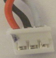
The USRP E312 (and with upgraded firmware E310) supports LiIon Battery packs (e.g. AA Portable Power Corp, 749801-01).
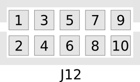
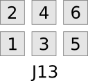
The connector J1 on E312's motherboard is a Molex 53014-6310. The corresponding mating connector is a Molex 51004-0300.
The pins are as follows:
The battery information is exposed on the device via the sysfs directory under:
/sys/class/power_supply/BAT/
and for the charger:
/sys/class/power_supply/AC/
The values can be accessed via libudev or manually e.g.:
root@ettus-e3xx: cat /sys/class/power_supply/BAT/status
The driver emits uevents on changes, that can be used to write custom UDev rules. Using UDev rules one can configure the USRP E3xx to shut down on certain events, such as low battery charge, high temperatures or AC power plug in.
The following example will cause the system to shut down at a reported temperature of 73C:
Another example will cause a safe shutdown once the battery level reaches 5 percent
For more information, please see the udev manual pages and Kernel Power Supply Docs .
In order for the fuel gauge to give a usable indication of remaining charge it needs to be calibrated. The procedure for calibration is as follows:
A faster (less accurate) calibration procedure is as follows:
Type:
$ echo 3200000 > /sys/class/power_supply/BAT/charge_now
The USRP E310 MIMO XCVR daughterboard features an integrated MIMO capable RF frontend.
The RF frontend has individually tunable receive and transmit chains. Both transmit and receive can be used in a MIMO configuration. For the MIMO case, both receive frontends share the RX LO, and both transmit frontends share the TX LO. Each LO is tunable between 50 MHz and 6 GHz.
All frontends have individual analog gain controls. The receive frontends have 76 dB of available gain; and the transmit frontends have 89.5 dB of available gain. Gain settings are application specific, but it is recommended that users consider using at least half of the available gain to get reasonable dynamic range.
The frontends provide a lo-locked sensor that can be queried through the UHD API.
The transmit and receive filter banks uses switches to select between the available filters. These paths are also dependent on the antenna switch settings. Incorrectly setting the switches generally results in attenuated input / output power. Receive filters are band pass (series high & low pass filters), transmit filters are low pass.
Source code related to controlling the filter band and antenna switches resides in e300_impl.c. Specifically, refer to methods e300_impl::_update_bandsel, e300_impl::_update_atrs, e300_impl::_update_gpio, and e300_impl::_update_enables. Generally, these methods set the switches depending on the state of transmit and receive streams.
The following sections provide switch setting tables for antenna and filter selection for frontends A & B receive and transmit paths. For futher details refer to the schematics.
Note: X = don't care, T = If full duplex, set bits according to transmit table, otherwise don't care. Filter range A – B will be selected if A <= freq < B.
Receive
| RX Port | RX Filter (MHz) | VCTXRX2_V1,V2 | VCRX2_V1,V2 | RX2_BANDSEL[2:0] | RX2B_BANDSEL[1:0] | RX2C_BANDSEL[1:0] |
|---|---|---|---|---|---|---|
| TRX-A | < 450 | 01 | 10 | 101 | XX | 01 |
| TRX-A | 450 – 700 | 01 | 10 | 011 | XX | 11 |
| TRX-A | 700 – 1200 | 01 | 10 | 001 | XX | 10 |
| TRX-A | 1200 – 1800 | 01 | 10 | 000 | 01 | XX |
| TRX-A | 1800 – 2350 | 01 | 10 | 010 | 11 | XX |
| TRX-A | 2350 – 2600 | 01 | 10 | 100 | 10 | XX |
| TRX-A | 2600 – 6000 | 01 | 01 | XXX | XX | XX |
| RX2-A | 70 – 450 | TT | 01 | 101 | XX | 01 |
| RX2-A | 450 – 700 | TT | 01 | 011 | XX | 11 |
| RX2-A | 700 – 1200 | TT | 01 | 001 | XX | 10 |
| RX2-A | 1200 – 1800 | TT | 01 | 000 | 01 | XX |
| RX2-A | 1800 – 2350 | TT | 01 | 010 | 11 | XX |
| RX2-A | 2350 – 2600 | TT | 01 | 100 | 10 | XX |
| RX2-A | >= 2600 | TT | 10 | XXX | XX | XX |
Transmit
| TX Port | TX Filter (MHz) | VCTXRX2_V1,V2 | TX_ENABLE2A,2B | TX_BANDSEL[2:0] |
|---|---|---|---|---|
| TRX-A | < 117.7 | 10 | 01 | 111 |
| TRX-A | 117.7 – 178.2 | 10 | 01 | 110 |
| TRX-A | 178.2 – 284.3 | 10 | 01 | 101 |
| TRX-A | 284.3 – 453.7 | 10 | 01 | 100 |
| TRX-A | 453.7 – 723.8 | 10 | 01 | 011 |
| TRX-A | 723.8 – 1154.9 | 10 | 01 | 010 |
| TRX-A | 1154.9 – 1842.6 | 10 | 01 | 001 |
| TRX-A | 1842.6 – 2940.0 | 10 | 01 | 000 |
| TRX-A | >= 2940.0 | 11 | 10 | XXX |
Note: Although the transmit filters are low pass, this table describes UHD's tuning range for selecting each filter path. The table also includes the required transmit enable state.
Note: X = don't care, T = If full duplex, set bits according to transmit table, otherwise don't care. Filter range A – B will be selected if A <= freq < B.
Receive
| RX Port | RX Filter (MHz) | VCTXRX1_V1,V2 | VCRX1_V1,V2 | RX1_BANDSEL[2:0] | RX1B_BANDSEL[1:0] | RX1C_BANDSEL[1:0] |
|---|---|---|---|---|---|---|
| TRX-B | < 450 | 10 | 01 | 100 | XX | 10 |
| TRX-B | 450 – 700 | 10 | 01 | 010 | XX | 11 |
| TRX-B | 700 – 1200 | 10 | 01 | 000 | XX | 01 |
| TRX-B | 1200 – 1800 | 10 | 01 | 001 | 10 | XX |
| TRX-B | 1800 – 2350 | 10 | 01 | 011 | 11 | XX |
| TRX-B | 2350 – 2600 | 10 | 01 | 101 | 01 | XX |
| TRX-B | 2600 – 6000 | 10 | 10 | XXX | XX | XX |
| RX2-B | 70 – 450 | TT | 10 | 100 | XX | 10 |
| RX2-B | 450 – 700 | TT | 10 | 010 | XX | 11 |
| RX2-B | 700 – 1200 | TT | 10 | 000 | XX | 01 |
| RX2-B | 1200 – 1800 | TT | 10 | 001 | 10 | XX |
| RX2-B | 1800 – 2350 | TT | 10 | 011 | 11 | XX |
| RX2-B | 2350 – 2600 | TT | 10 | 101 | 01 | XX |
| RX2-B | >= 2600 | TT | 01 | XXX | XX | XX |
Transmit
| TX Port | TX Filter (MHz) | VCTXRX1_V1,V2 | TX_ENABLE1A,1B | TX1_BANDSEL[2:0] |
|---|---|---|---|---|
| TRX-B | < 117.7 | 00 | 01 | 111 |
| TRX-B | 117.7 – 178.2 | 00 | 01 | 110 |
| TRX-B | 178.2 – 284.3 | 00 | 01 | 101 |
| TRX-B | 284.3 – 453.7 | 00 | 01 | 100 |
| TRX-B | 453.7 – 723.8 | 00 | 01 | 011 |
| TRX-B | 723.8 – 1154.9 | 00 | 01 | 010 |
| TRX-B | 1154.9 – 1842.6 | 00 | 01 | 001 |
| TRX-B | 1842.6 – 2940.0 | 00 | 01 | 000 |
| TRX-B | >= 2940.0 | 11 | 10 | XXX |
Note: Although the transmit filters are low pass, the following table describes UHD's tuning range for selecting each filter path. The table also includes the required transmit enable states.
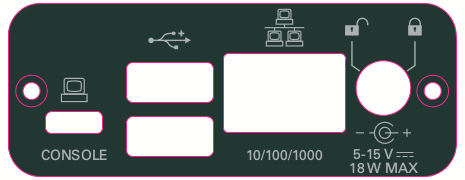
Your USRP E3XX Series device can be configured by editing the /etc/network/interfaces.
The device defaults to DHCP, meaning it will query the local network's DHCP server for an address.
The default configuration should look similar to, instructing your device to query local DHCP servers for an IP address, gateway, etc.
In order to change the hostname used to obtain an IP address via DHCP change
/etc/hostname
and edit:
/etc/network/interfaces
Note: In rare occasions it might be necessary to increase the timeout value for the dhcp client running on the device in order for autoconfiguration to succeed.
In order to increase the timeout to e.g. 40 seconds edit:
/etc/network/interfaces
To configure a static IP address edit
/etc/network/interfaces
to look like
There are two complete DDC and DUC DSP chains in the FPGA. In the single channel case, only one chain is ever used. To receive / transmit from both channels, the user must set the RX or TX subdevice specification.
In the following example, a E310 MIMO XCVR is installed. Channel 0 is sourced from subdevice A, and channel 1 is sourced from subdevice B
The following sensors are available for the USRP-E Series motherboards; they can be queried through the API.
Your USRP-E series device can be used in network mode for narrow band signal observation, evaluation and debugging purposes. See the instructions below for how to use network mode.
Please note that when compared with normal operation as a standalone device the usable bandwidth is limited and therefore Network Mode is not the recommended mode of operation.
To work with your E-Series device in network mode, you will need to build UHD on your PC with extra CMake flags. Assuming you are in the host/build directory, see below:
    $ cmake -DENABLE_E300=ON -DE300_FORCE_NETWORK=ON ..
    $ make
Once UHD is installed on your device, it will be able to interact with an E-Series device with network mode active (see below).
In order to use the device in network mode it is necessary to start the usrp_e3x0_network_mode executable on the device. In order to start the executable please log into your device either via SSH or serial console(see First boot) and type
$ usrp_e3x0_network_mode
Your device should now be discoverable by your host computer via the usual UHD tools. If you are having trouble communicating with your device see the Communication Problems section.
In a single-device configuration, the USRP device must have a unique IPv4 address on the host computer. The USRP can be identified through its IPv4 address or resolvable hostname. See the application notes on Device Identification. Use this addressing scheme with the uhd::usrp::multi_usrp interface (not a typo!).
Example device address string representation for a USRP-E Series device with IPv4 address 192.168.10.2:
addr=192.168.10.2
In a multi-device configuration, each USRP device must have a unique IPv4 address on the host computer. The device address parameter keys must be suffixed with the device index. Each parameter key should be of the format <key><index>. Use this addressing scheme with the uhd::usrp::multi_usrp interface.
Example device address string representation for 2 USRPs with IPv4 addresses 192.168.10.2 and 192.168.20.2:
addr0=192.168.10.2, addr1=192.168.20.2
Booting your device from a NFS root might be desirable for remote deployment, management or similar applications.
Requirements:
The first step to make a root filesystem available via NFS is to extract the root file system. This can be done as follows:
$ sfdisk -l -uS <your-image>.direct
Which should produce output similar to:
Disk release3-image.direct: 7 GiB, 7516197888 bytes, 14680074 sectors
Units: sectors of 1 * 512 = 512 bytes
Sector size (logical/physical): 512 bytes / 512 bytes
I/O size (minimum/optimal): 512 bytes / 512 bytes
Disklabel type: dos
Disk identifier: 0x8bc3587b

Device                 Boot Start      End  Sectors Size Id Type
release3-image.direct1 *        8    36871    36864  18M  c W95 FAT32 (LBA)
release3-image.direct2      36872 14680071 14643200   7G 83 Linux
From this one can see the second partition (root filesystem) starts at sector 36872, and has a length of 14680071. We can use the dd tool to extract the root filesystem into a handy file.
$ dd if=<yourimage>.direct of=<yourimage_rootfs>.direct offset=36872 count=14643200
The same procedure can be done for the boot partition.
$ dd if=<yourimage>.direct of=<yourimage_boot>.direct offset=8 count=36864
Both of these files are mountable on your NFS server, e.g. by:
$ mount <yourimage_rootfs>.direct /srv/nfs/root-e3xx
$ mount <yourimage_rootfs>.direct /srv/nfs/root-e3xx/media/FAT
Copy the uImage, uEnv.txt, u-boot.img, boot.bin from the extracted boot partition to the boot partition of your device's card.
Use the devicetree compiler to modify e300-devicetree.dtb file as follows:
$ dtc -I dtb -O dts e300-devicetree.dtb -o e300-devicetree.dts
Using your editor of choice modify the chosen property in e300-devicetree.dts from:
console=ttyPS0,115200 root=/dev/mmc0blkp2 rw rootwait earlyprintk
to:
console=ttyPS0,115200 root=/dev/nfs rw nfsroot=<yourserverip>:<yourpath>,vers=3 rootwait ip=dhcp earlyprintk
Use the devicetree compiler to compile the modified devicetree as follows:
$ dtc e300-devicetree.dts -o e300-devicetree.dtb
Copy the modified e300-devicetree.dtb to your device's card.
For more information on server configuration please refer to your Linux distribution's NFS Server manual, for more information about NFS root see the Linux Kernel NFS Root documentation
When setting up a development machine for the first time, you may have various difficulties communicating with the USRP device. The following tips are designed to help narrow down and diagnose the problem.
This is a common error that occurs when you have set the subnet of your network interface to a different subnet than the network interface of the USRP device. For example, if your network interface is set to 192.168.20.1, and the USRP device is 192.168.10.2 (note the difference in the third numbers of the IP addresses), you will likely see a 'no control response' error message.
Fixing this is simple - just set the your host PC's IP address to the same subnet as that of your USRP device. Instructions for setting your IP address are in the previous section of this documentation.
When the IP address is not specified, the device discovery broadcasts UDP packets from each Ethernet interface. Many firewalls will block the replies to these broadcast packets. If disabling your system's firewall or specifying the IP address yields a discovered device, then your firewall may be blocking replies to UDP broadcast packets. If this is the case, we recommend that you disable the firewall or create a rule to allow all incoming packets with UDP source port 49152.
The USRP device will reply to ICMP echo requests ("ping"). A successful ping response means that the device has booted properly and that it is using the expected IP address.
ping 192.168.10.2
Use Wireshark to monitor packets sent to and received from the device.
When there is network traffic arriving at the Ethernet port, LEDs will light up. You can use this to make sure the network connection is correctly set up, e.g. by pinging the USRP and making sure the LEDs start to blink.
/etc/ssh/sshd_config, uncomment the line #X11Forwarding no and change "no" to "yes".With Firmware 2.0 the device no longer turns on when AC power is plugged.
This setting can be adjusted via /sys/devices/axi_pmu.3/autoboot.
Using $ echo 1 > /sys/devices/axi_pmu.3/autoboot autoboot is turned on.
Using $ echo 0 > /sys/devices/axi_pmu.3/autoboot autoboot is turned off.
Note that the path above is subject to change depending on device tree changes.
OpenBTS allows the USRP E310 to serve as a GSM base station capable of providing voice and messaging services to standard GSM handsets. General information on the OpenBTS project can be found at the official webpage.
Special instructions to install OpenBTS on the E310 can be found on the OpenBTS wiki.
 1.8.13