|
USRP Hardware Driver and USRP Manual
Version: 4.9.0.0
UHD and USRP Manual
|


|
|
USRP Hardware Driver and USRP Manual
Version: 4.9.0.0
UHD and USRP Manual
|
|
There are two category of devices in the E3xx series.
These devices have some differences in their hardware capabilities but both are 2-channel transmitter/receiver based on the AD9361 transceiver IC and provide two RF channels:
The E310/E312/E313 has a motherboard and a daughterboard in an enclosed module with one AD9361 IC with 2 RF channels.
The E320 is monolithic board with one AD9361 IC with 2 RF channels.
The main CPU of the E310 is a Xilinx Zynq SoC XC7Z020. It is both a dual-core ARM Cortex A9 CPU and Kintex-7 FPGA on a single die. The CPU is clocked at 667 MHz (speed grade 1) and 866 MHz (speed grade 3).
The programmable logic (PL, or FPGA) section of the SoC is responsible for handling all sampling data, DMA connections, and any other high-speed utility such as custom RFNoC logic. The processing system (PS, or CPU) is running a custom-build OpenEmbedded-based Linux operating system. The OS is responsible for all the device and peripheral management, such as running MPM (see section The Module Peripheral Manager (MPM) Architecture), running local, UHD sessions, etc.
This section covers the details for porting your E310 to the new MPM architecture. MPM is a hardware daemon running on the Linux operating system on the ARM cores and responsible for the device to function as a USRP.
A large portion of hardware-specific setup is handled by the daemon.
Note that the SD cards shipped with E310s do not contain the latest filesystem images. In order to use MPM (see section The Module Peripheral Manager (MPM) Architecture) and all its features, the SD cards need to be manually flashed. Refer to Updating the SD card in order to upgrade to E310 with UHD v3.15.0.0 or above.
After updating the SD card, you should be able to connect your device to the host OS either via SSH or serial console. See sections SSH connection and Serial connection respectively, for more details.
Once you are logged in on the device, you should be able to run uhd_usrp_probe or other UHD examples.
Here is a list of a changes with the latest E310 filesystem (UHD v3.15.0.0 and later) that can affect customer usage and applications:
ni-e31x-$serial. This makes it easier to identify devices. You can change the hostname by creating the file /data/network/hostname, saving the desired hostname in it, then rebooting.FPGA bit/bin/rpt file name and image target:
| FPGA type | Old filename | New filename |
|---|---|---|
| IDLE Image (power saving mode) SG1 | usrp_e3xx_fpga_idle.bit | usrp_e310_sg1_idle_fpga.bit |
| IDLE Image (power saving mode) SG3 | usrp_e3xx_fpga_idle_sg3.bit | usrp_e310_sg3_idle_fpga.bit |
| NORMAL Image SG1 | usrp_e310_fpga.bit | usrp_e310_sg1_fpga.bit |
| NORMAL Image SG3 | usrp_e310_fpga_sg3.bit | usrp_e310_sg3_fpga.bit |
The names of the FPGA build targets have been modified but the old FPGA targets would continue to work as before. The generated bit files names in the build directory will be new as mentioned above.
The main CPU of the E320 is a Xilinx Zynq SoC XC7Z045. It is both a dual-core ARM Cortex A9 CPU and Kintex-7 FPGA on a single die. The CPU is clocked at 1GHz (speed grade 3).
The programmable logic (PL, or FPGA) section of the SoC is responsible for handling all sampling data, the 1/10 GigE network connections, and any other high-speed utility such as custom RFNoC logic. The processing system (PS, or CPU) is running a custom-build OpenEmbedded-based Linux operating system. The OS is responsible for all the device and peripheral management, such as running MPM (see section The Module Peripheral Manager (MPM) Architecture), configuring the network interfaces, running local UHD sessions, etc.
It is possible to connect to the host OS either via SSH or serial console (see sections SSH connection and Serial connection, respectively).
The STM32 microcontroller controls various low-level features of the E320 series motherboard: It controls the power sequencing, reads out fan speeds and some of the temperature sensors. It is connected to the Zynq via an I2C bus.
It is possible to log into the STM32 using the serial interface (see Connecting to the microcontroller). This will allow certain low-level controls, such as remote power cycling should the CPU have become unresponsive for whatever reason.
The USRP E320 Series devices has an SFP+ port for Ethernet. Because the SFP+ port supports both 1 Gigabit (SFP) and 10 Gigabit (SFP+) transceivers, several FPGA images are shipped with UHD to determine the behavior of the interface.
| FPGA Image Flavor | SFP+ Port 0 Interface |
|---|---|
| 1G (Default) | 1 Gigabit Ethernet |
| XG | 10 Gigabit Ethernet |
| AA | Aurora |
The Aurora image can be used to run BISTs on the SFP.
Images can be updated and swapped using the image loader tool. First, make sure your version of UHD is running the correct images by downloading them from the internet:
[sudo] uhd_images_downloader
Then, use the image loader tool to pick an FPGA image:
uhd_image_loader --args type=e3xx,addr=<IP Address>,fpga=XG
The E310/E312/E313/E320 use a micro SD card as its main storage. The entire root file system (Linux kernel, libraries) and any user data are stored on this SD card.
The SD card is partitioned into four partitions:
Note: It is possible to access the currently inactive root file system by mounting it. After logging into the device using serial console or SSH (see the following two sections), run the following commands:
$ mkdir temp
$ mount /dev/mmcblk0p3 temp
$ ls temp # You are now accessing the idle partition:
bin   data  etc   lib         media  proc  sbin  tmp    usr
boot  dev   home  lost+found  mnt    run   sys   uboot  var
The device node in the mount command will likely differ, depending on which partition is currently already mounted.
This will run you through the first steps relevant to getting your USRP E3XX up and running. Note: This guide was creating on an Ubuntu machine, and other distributions or OS's may have different names/methods.
Unlike the X300 or N200 series, there is no assembly required for all E3xx devices as E310 motherboard and daughterboard comes in an enclosure and E320, on the other hand is a monolithic board (in board-only version) or comes in an enclosure.
Checklist:
The SD cards shipped with E310s do not contain the latest filesystem images. In order to use MPM and all its features, the SD cards need to be manually flashed. Refer to Updating the SD card in order to upgrade to E310 with UHD v3.15.0.0 or above. Once it has been upgraded to the new filesystem, Mender can be used to remotely update the filesystems. For details on using Mender, see Section Mender: Remote update capability.
Before doing any major work with a newly acquired USRP E320, it is recommended to update the file system. For the OEM/Board-only version of E320, the SD card is physically accessible and filesystem update can be accomplished directly by using Mender or externally by manually writing an image onto a micro SD card and inserting it. For the enclosure version of E320, Mender update is required as there is no direct physical access to the device. For details on using Mender, see Section Mender: Remote update capability .
Manual updating is simply loading an image on the micro SD card. The first step in that process is to obtain an image.
To obtain the default micro SD card image for a specific version of UHD, install that version of UHD (E320 - 3.13.0.2 or later, E310 - 3.15.0.0 or later) on a host system with Internet access and run:
$ uhd_images_downloader -t <e310/e320> -t sdimg
The image will be downloaded to <UHD_INSTALL_DIR>/share/uhd/images/usrp_<e310/e320>_fs.sdimg, where <UHD_INSTALL_DIR> is the UHD installation directory.
To load an image onto the micro SD card, connect the card to the host and run:
$ sudo dd if=<YOUR_IMAGE> of=/dev/<YOUR_SD_CARD> bs=1M
The <YOUR_IMAGE> is the path to the micro SD card image (i.e.<UHD_INSTALL_DIR>/share/uhd/images/usrp_<e310/e320>_fs.sdimg).
The <YOUR_SD_CARD> device node depends on your operating system and which other devices are plugged in. Typical values are sdb or mmcblk0.
CAUTION: The Linux utility dd or bmap can cause unrecoverable data loss if the incorrect disk is selected, or if the parameters are input incorrectly. Ensure you have selected the correct input and output parameters for your system configuration.
Manual loading a file system image on to micro SD card is straight forward on Windows with the use of 3rd party utilities available online. One is the open source, cross-platform utility Etcher, that is also available for macOS and x86 Linux. Follow the steps to load image on the micro SD card:
The micro SD card used can be the original SD card shipped with the device or another one that is at least 8GB for E310 and at least 16 GB for E320 in size.
Ettus Research provides SD card images at regular intervals, but there can be good reasons to build custom SD cards, e.g., to test the very latest UHD or MPM for which there has not been an SD card release, to add own applications to the SD card, or to run a modified version of UHD.
Note that building SD cards is very disk space and RAM intensive.
Ettus Research provides a Docker containers to facilitate building filesystems. Refer to the README for more details.
It is possible to gain root access to the device using a serial terminal emulator. Most Linux, OSX, or other Unix flavours have a tool called 'screen' which can be used for this purpose, by running the following command:
$ sudo screen /dev/ttyUSB2 115200
In this command, we prepend 'sudo' to elevate user privileges (by default, accessing serial ports is not available to regular users), we specify the device node (in this case, /dev/ttyUSB2), and the baud rate (115200).
The exact device node depends on your operating system's driver and other USB devices that might be already connected. Modern Linux systems offer alternatives to simply trying device nodes; instead, the OS might have a directory of symlinks under /dev/serial/by-id:
For E310:
$ ls /dev/serial/by-id
/dev/serial/by-id/usb-FTDI_FT230X_Basic_UART_DQ0041HO-if00-port0
For E320:
$ ls /dev/serial/by-id
/dev/serial/by-id/usb-FTDI_Dual_RS232-HS-if00-port0
/dev/serial/by-id/usb-FTDI_Dual_RS232-HS-if01-port0
/dev/serial/by-id/usb-Silicon_Labs_CP2105_Dual_USB_to_UART_Bridge_Controller_007F6A6C-if00-port0
/dev/serial/by-id/usb-Silicon_Labs_CP2105_Dual_USB_to_UART_Bridge_Controller_007F6A6C-if01-port0
Note: Exact names depend on the host operating system version and may differ.
Every E310 device connected to USB will by default show up as one device. The device labeled "FTDI_FT230X_Basic_UART_DQ0041HO" connects to Linux.
Every E320 device connected to USB will by default show up as four different devices. The devices labeled "USB_to_UART_Bridge_Controller" are the devices that offer a serial prompt. The one with the if01 suffix connects to Linux, whereas the one with if00 suffix connects to the STM32 microcontroller. If you have multiple E320 devices connected, you may have to try out multiple devices. In this case, to use this symlink instead of the raw device node address, modify the command above to:
For E310:
$ sudo screen /dev/serial/by-id/usb-FTDI_FT230X_Basic_UART_DQ0041HO-if00-port0 115200
For E320:
$ sudo screen /dev/usb-Silicon_Labs_CP2105_Dual_USB_to_UART_Bridge_Controller_007F6A6C-if01-port0 115200
You should be presented with a shell prompt similar to the following:
root@ni-<e31x/e320>-<serial>:~#
On this prompt, you can enter any Linux command available. Using the default configuration, the serial console will also show all kernel log messages (unlike when using SSH, for example), and give access to the boot loader (U-boot prompt). This can be used to debug kernel or bootloader issues more efficiently than when logged in via SSH.
The STM32 microcontroller (which controls the power sequencing, among other things) also has a serial console available. To connect to the microcontroller, use the other UART device. In the example above:
$ sudo screen /dev/usb-Silicon_Labs_CP2105_Dual_USB_to_UART_Bridge_Controller_007F6CB5-if00-port0 115200
It provides a very simple prompt. The command 'help' will list all available commands. A direct connection to the microcontroller can be used to hard-reset the device without physically accessing it (i.e., emulating a power button press) and other low-level diagnostics.
The USRP E310 devices have just one network connection: RJ-45 connector while the USRP E320 has two network connections: One SFP port, and an RJ-45 connector.
The RJ-45 connection is by default configured by DHCP; by plugging it into a 1 Gigabit switch on a DHCP-capable network, it will get assigned an IP address and thus be accessible via ssh.
In case your network setup does not include a DHCP server, refer to the section Serial connection. A serial login can be used to assign an IP address manually.
After the device obtained an IP address you can log in from a Linux or OSX machine by typing:
$ ssh root@ni-<e31x/e320>-<serial> # Replace with your actual device name!
Depending on your network setup, using a .local domain may work:
$ ssh root@ni-<e31x/e320>-<serial>.local
Of course, you can also connect to the IP address directly if you know it (or set it manually using the serial console).
Note: The device's hostname is derived from its serial number by default (ni-<e31x/e320>-<SERIAL>). You can change the hostname by creating the file /data/network/hostname, saving the desired hostname in it, then rebooting.
On Microsoft Windows, the connection can be established using a tool such as Putty, by selecting a username of root without password.
Like with the serial console, you should be presented with a prompt like the following:
root@ni-<e31x/e320>-<serial>:~#
The RJ45 port (eth0) comes up with a default configuration of DHCP, that will request a network address from your DHCP server (if available on your network).
The factory settings are as follows:
eth0 (DHCP):

    [Match]
    Name=eth0

    [Network]
    DHCP=v4

    [DHCPv4]
    UseHostname=false
E320 has an extra SFP+ (sfp0) port which is configured with static address 192.168.10.2/24. The configuration for the sfp0 port is stored in /data/network/sfp0.network.
For configuration please refer to the systemd-networkd manual pages
The factory settings are as follows:
sfp0 (static):

    [Match]
    Name=sfp0

    [Network]
    Address=192.168.10.2/24

    [Link]
    MTUBytes=9000
Note: Care needs to be taken when editing these files on the device, since vi / vim sometimes generates undo files (e.g. /data/network/sfp0.network~), that systemd-networkd might accidentally pick up.
Note: Temporarily setting the IP addresses via ifconfig etc will only change the value until the next reboot or reload of the FPGA image.
With UHD 4.0 the RJ-45 port can also be used for streaming samples from the USRP device to the host or other remote operations such as uhd_image_loader. Please note: As the SDR application runs on an embedded CPU with limited processing capability, users should leverage the FPGA using tools such as RFNoC to offload compute intensive algorithms that process high bandwidth samples. The maximum sample rates that can be achieved are 4.4 MS/s on the E31x and 6.4 MS/s on the E320 when streaming through the RJ-45 port. As the E320 has an additional highspeed SFP Port, the RJ-45 port should only be used for streaming data from the E320 if necessary.
The streaming sample rates can be tested and verified using the UHD example benchmark_rate:
/path/to/benchmark_rate --args addr=<e3xx-ip-address>,master_clock_rate=<master_clock_rate> --rx_rate=<rx_rate>
To verify maximum streaming rates, the following configuration should be used:
master_clock_rate=13.2e6, rx_rate=4.4e6master_clock_rate=19.6e6, rx_rate=6.4e6The E320 ships without a root password set. It is possible to ssh into the device by simply connecting as root, and thus gaining access to all subsystems. To set a password, run the command
$ passwd
on the device.
Updating the FPGA follows the same procedure as other USRPs. Use the uhd_image_loader command line utility to upload a new FPGA image onto the device. The command can be run on the host to load the image via RJ-45 network connection or it can be run on the device.
A common reason to update the FPGA image is in the case of a UHD/FPGA compat number mismatch (for example, if UHD has been updated, and now expects a newer version of the FPGA than is on the device). In this case, simply run
$ uhd_images_downloader
to update the local cache of FPGA images. Then, run
$ uhd_image_loader --args type=e3xx,addr=ni-<e31x/e320>-<serial>
to update the FPGA using the default settings. Replace the addr above with the correct device address. If a custom FPGA image is targeted for uploading, use the --fpga-path command line argument. Run
$ uhd_image_loader --help
to see a full list of command line options. Note that updating the FPGA image will force a reload of the FPGA, and in case of E320 it will temporarily take down the SFP network interfaces (and temporary settings, such as applied via ifconfig on the command line, will be lost).
Like any other USRP, all E series USRPs are controlled by the UHD software. To integrate a USRP E310/E312/E313/E320 into your C++ application, you would generate a UHD device in the same way you would for any other USRP:
For a list of which arguments can be passed into make(), see Section Device arguments.
| Key | Description | Example Value |
|---|---|---|
| addr | IPv4 address of primary SFP+/RJ-45 port to connect to | addr=192.168.30.2 |
| find_all | When using broadcast, find all devices, even if unreachable via CHDR. | find_all=1 |
| master_clock_rate | Master Clock Rate in Hz. Default is 16 MHz. | master_clock_rate=30.72e6 |
| skip_init | Skip the initialization process for the device. | skip_init=1 |
| discovery_port | Override default value for MPM discovery port. | discovery_port=49700 |
| rpc_port | Override default value for MPM RPC port. | rpc_port=49701 |
| enable_gps | Enable/disable power to the integrated GPSDO (E320 only). | enable_gps=0 |
Like other USRPs, the E3x0 series has RF and motherboard sensors. When using uhd::usrp::multi_usrp, the following API calls are relevant to interact with the sensor API:
The following motherboard sensors are always available:
temp_fpga: temperature (in Celsius) of the FPGA dietemp_mb: temperature (in Celsius) of the motherboardref_locked: This will check that all the daughter boards have locked to the reference clock.The following daughterboard sensors are always available:
lo_locked: Boolean sensor value to check if the AD9361 LO has locked to its referencelo_lock: Alias to lo_locked (for backward compatibility reasons)ad9361_temperature: Temperature sensor of the RFIC dierssi: RSSI value as returned from the AD9361 (RX only)The following motherboard sensors are always available:
temp_internal: temperature (in Celsius) of Temperature Sensor on boardtemp_fpga: temperature (in Celsius) of the FPGA dietemp_rf_channelA: temperature (in Celsius) near power amplifier RF Atemp_rf_channelB: temperature (in Celsius) near power amplifier RF Btemp_main_power: temperature (in Celsius) near power supplygps_locked: GPS lockgps_time: GPS time in seconds sin ce the epchgps_tpv: A TPV report from GPSd serialized as JSONgps_sky: A SKY report from GPSd serialized as JSONref_locked: This will check that all the daughter boards have locked to the external/internal reference clock.fan: get fan speed (in rpm)The following daughterboard sensors are always available:
lo_locked: Boolean sensor value to check if the AD9361 LO has locked to its referencelo_lock: Alias to lo_locked (for backward compatibility reasons)ad9361_temperature: Temperature sensor of the RFIC dierssi: RSSI value as returned from the AD9361 (RX only)The E3xx series support the UHD power calibration API (see: Power Level Controls). The TX path and the two RX paths per channel each have their own calibration data, resulting in 6 sets of calibration data per E3xx device.
Devices have to be manually calibrated using a calibrated power meter or signal generator.
Mender is a third-party software that enables remote updating of the root file system without physically accessing the device (see also the Mender website). Mender can be executed locally on the device, or a Mender server can be set up which can be used to remotely update an arbitrary number of USRP devices. Mender servers can be self-hosted, or hosted by Mender (see mender.io for pricing and availability).
When updating the file system using Mender, the tool will overwrite the root file system partition that is not currently mounted (note: every SD card comes with two separate root file system partitions, only one is ever used at a single time). Any data stored on that partition will be permanently lost. After updating that partition, it will reboot into the newly updated partition. Only if the update is confirmed by the user, the update will be made permanent. This means that if an update fails, the device will be always able to reboot into the partition from which the update was originally launched (which presumably is in a working state). Another update can be launched now to correct the previous, failed update, until it works. See also Section The SD card.
Note: For E310, the SD cards that are shipped with the device do not have the latest UHD and do not support MPM by default. The SD cards will have to be flashed with UHD v3.15.0.0 or above to be able to use mender. After the first upgrade, mender can be used for future upgrades. Refer to the migration guide. E310 Migration Guide to MPM architecture
To initiate an update from the device itself, download a Mender artifact containing the update itself. These are files with a .mender suffix.
Then run mender on the command line:
$ mender install /path/to/latest.mender
The artifact can also be stored on a remote server:
$ mender install http://server.name/path/to/latest.mender
This procedure will take a while. After mender has logged a successful update, reboot the device:
$ reboot
If the reboot worked, and the device seems functional, commit the changes so the boot loader knows to permanently boot into this partition:
$ mender commit
To identify the currently installed Mender artifact from the command line, run the following command:
$ mender show-artifact
If you are running a hosted server, the updates can be initiated from a web dashboard. From there, you can start the updates without having to log into the device, and can update groups of USRPs with a few clicks in a web GUI. The dashboard can also be used to inspect the state of USRPs. This is a simple way to update groups of rack-mounted USRPs with custom file systems.
Salt (also known as SaltStack, see Salt Website) is a Python-based tool for maintaining fleets of remote devices. It can be used to manage USRP E31X/E320 remotely for all types of settings that are not controlled by UHD. For example, if an operator would like to reset the root password on multiple devices, or install custom software, this tool might be a suitable choice.
Salt is a third-party project with its own documentation, which should be consulted for configuring it. However, the Salt minion is installed by default on every E31X/E320 device. To start it, simply log on to the device and run:
$ systemctl start salt-minion
To permanently enable it at every boot, run (this won't by itself launch the salt-minion):
$ systemctl enable salt-minion
To make use of Salt, both the device needs to be configured (the "minion") and, typically, a server to act as the Salt master. Refer to the Salt documentation on how to configure the minion and the master. A typical sequence to get started will look like this:
apt install salt-master if the server is an Ubuntu system), and make sure the Salt master is running./etc/salt/minion file on the device by editing the master: line.systemctl start salt-minion.salt-key -a $hostname where $hostname is the name of the minion.Note: Do not source high currents (more than 5 mA) per pin. The GPIOs are not designed to drive high loads!
Note: Unlike the X300 series, the E3XX series does not have user-programmable daughterboard GPIOs. The front-panel (or internal) GPIOs can still be used to track the ATR state of the radios, though (see below).
The USRP E310 has 6 programmable GPIO pins, accessible through an internal connector (see also Internal GPIO). The E320 has 8 GPIO pins, accessible through the HDMI connector (see Front Panel GPIO).
These GPIOs have a programmable source per pin. For every pin, it is possible to either drive it from the PS (i.e., from Linux), or via UHD.
When UHD is driving a pin, both of the radio channels can drive the GPIO pin. In that case, the pin can either track the ATR register of that radio channel, or it can be freely programmed.
When the PS is driving the pin, UHD releases control of the GPIO pin and it can be programmed from Linux using udev.
The following example demonstrates how the GPIO can be used:
The E320 series devices have a built-in self-test that can be used to verify the hardware. It is not automatically run, but it can be invoked anytime by running the e320_bist executable. Calling
e320_bist -h
will list the available options. Tests can be run by specifying their name, e.g.
e320_bist gpsdo
will test the functionality of the GPSDO. Calling e320_bist standard will run a standard set of tests, verifying some base peripherals such as the RTC, the fan and temperature sensors, etc.
Some tests require special hardware connected. For example, for the sfp_loopback tests, a loopback module must be plugged into the SFP+.
Tests may also load different FPGA images, if required. The aforementioned SFP tests will load the Aurora FPGA image and use Aurora to run the BER tests on the SFP port. This is particularly relevant if either a custom image was loaded, or if there is an active SSH or other connection coming in via the SFP+ ports.
All E series devices are on the MPM architecture (see also: The Module Peripheral Manager (MPM) Architecture). Inside the Linux operating system running on the ARM cores, there is a hardware daemon which needs to be active in order for the device to function as a USRP (it is enabled to run by default).
A large portion of hardware-specific setup is handled by the daemon.
E320 devices ship with all relevant software installed on the SD card. Updating UHD and/or MPM on the SD card is typically easiest done by updating the filesystem image (see Section Mender: Remote update capability). However, it is certainly possible to compile UHD and MPM by hand, e.g., in order to modify and try out changes without having to build entire filesystems in between. At Ettus R&D, this mode of operation is often used for rapid iteration cycles.
While on E310 the SD cards that are shipped with the device do not have the latest UHD and do not support MPM by default. The SD cards will have to be flashed with UHD v3.15.0.0 or above to be able to use mender. After the first upgrade, mender can be used for future upgrades. Refer to the migration guide. E310 Migration Guide to MPM architecture
In general, compiling natively is not a recommended way of compiling code for the ARM processors. However, in the case of MPM, the amount of C++ code that needs to be compiled is very little, and a full compile of MPM will take a few minutes even on the device. First, you need to get a copy of the MPM source code onto your device. If you have an internet connection, you can use git to pull it directly from the Ettus repository (all commands are run on the device itself, inside the home directory):
$ git clone https://github.com/EttusResearch/uhd.git
You can also SSHFS it from another computer:
$ mkdir uhd # Create a new, empty directory called uhd
$ sshfs user@yourcomputer:src/uhd uhd # This will mount ~/src/uhd from the remote machine to ~/uhd on the device
Now, create a build directory and use the regular cmake/make procedure to kick off a build. It can be advantageous (especially for slow network connections) to create the build directory outside of the repository directory:
$ mkdir build_mpm
$ cd build_mpm # You are now in /home/root/build_mpm
$ cmake -DMPM_DEVICE=e320 ../uhd/mpm
$ make -j2 install # This will take several minutes
Note that this overwrites your system MPM. You can install MPM to another location by specifying -DCMAKE_INSTALL_PREFIX, but make sure to update all of your paths appropriately.
If you prefer cross-compiling MPM the same way as UHD, refer to the following sections and adapt the instructions for UHD appropriately.
The recommended way to develop software for the E31X/E320 is to cross-compile. By running the compiles on a desktop or laptop computer, you will be able to speed up compile times considerably (compiling UHD natively would take many hours).
SDKs are distributed along with other binaries. They contain a cross-compiler, a cross-linker, a cross-debugger, and all the libraries available on the device to mirror its environment. Note: The SDK for E310 has been updated for UHD versions above v.3.15.0.0. Refer to the migration guide for details. E310 Migration Guide to MPM architecture
To unpack the SDK, simply execute it after downloading it:
$ cd /usr/local/share/uhd/images # Change this to where your images are stored
$ ./oecore-x86_64-cortexa9hf-neon-toolchain-nodistro.0.sh
If this doesn't work, the executable permissions of the file might have been lost (this can occur with some versions of Python). In that case, add those permissions back before executing the .sh file:
$ chmod +x oecore-x86_64-cortexa9hf-neon-toolchain-nodistro.0.sh
Executing the .sh file will prompt you for an installation path. Please ensure you have sufficient disk space, as each of the SDKs may require several gigabytes of disk space (depending on the image flavor selected).
This will allow you to compile UHD as well as (depending on the image flavor) other software.
Please note, that while several toolchains can be installed in parallel, they have to be installed to different directories.
Having installed the toolchain in the last step, in order to build software for your device open a new shell and type:
$ . $SDKPATH/environment-setup-armv7ahf-vfp-neon-oe-linux-gnueabi
This will modify the PATH, CC, CXX etc, environment variables and allow you to compile software for your device. To verify all went well you can try:
$ $CC -dumpmachine
which should return 'arm-oe-linux-gnueabi'.
 $ cmake -DCMAKE_TOOLCHAIN_FILE=../host/cmake/Toolchains/oe-sdk_cross.cmake -DCMAKE_INSTALL_PREFIX=/usr .. # Add any CMake options you desire
 $ make # You can run make -j12 to compile on 12 processes at once
Note: The UHD you are cross-compiling will not run on your host computer (the one where you're doing the development). Compiling UHD regularly on your host computer (with MPMD enabled) will allow you to talk to your device.
Several GNU Radio components depend on running binaries built for the build machine during compile. These binaries can be built and used for cross compiling, but this is an advanced topic.
The status LED in the power switch indicates the power and charge status. Its behavior is firmware version dependent.
Unlike most USRP devices, the E310 does not have independent reference clock and time source inputs. It is possible, however, to discipline the internal reference clock using an external time (PPS) source connected to the SYNC input pin. The E310 FPGA has a subsystem that can use the PPS signal from the SYNC pin or the internal GPS to align edges of the reference clock to edges of a shared PPS signal. This alignment happens automatically when the time source in UHD is set to "gpsdo" or "external". Please note that because the SYNC input can only accept a PPS signal, the only supported value for the reference clock source is "internal". Also, keep in mind that the E310 does not have a GPS-disciplined oscillator like other USRPs, the value "gpsdo" for the time source was chosen for compatibility with other USRPs.
Using a PPS signal for timestamp synchronization requires a LVCMOS or a 5V logic input signal. An external PPS can be used to discipline the internal reference clock. This feature is automatically enabled with the time source is set to "external".
To test the PPS input, you can use the following tool from the UHD examples:
<args> are device address arguments (optional if only one USRP device is on your machine)
cd <install-path>/lib/uhd/examples ./test_pps_input –args=<args>
Your USRP-E Series device comes with an internal GPS. In order to get a lock on a satellite an external GPS antenna is required. The PPS from the internal GPS can be used to discipline the internal reference clock. This feature is automatically enabled when the time source is set to "gpsdo". Again, keep in mind that while the E310 does not have an actual GPS-disciplined oscillator (GPSDO) on the board, the value "gpsdo" was named such for better compatibility with code written for other devices.
The device provides a 3.3V supply voltage to an external antenna connected to the GPS port of your device. Note that this supply voltage is turned off in order to save power upon destruction of the software object.
Pin 1 is connected to the shared +3.3V power rail and can be used to draw power. The maximum current depends on the power used by the rest of the device, but 300-500 mA is generally safe. It is recommended to monitor the rail voltage when drawing power from this pin.
Please see the GPIO API for information on configuring and using the GPIO bus.
Xilinx chipscope allows for debugging custom FPGA designs similar to a logic analyzer. USRP-E series devices can be used with Xilinx chipscope using the internal JTAG connector.
Further information on how to use Chipscope can be found in the Xilinx Chipscope Pro Software and Cores User Guide (UG029).
The USRP E312 (and with upgraded firmware E310) supports LiIon Battery packs (e.g. AA Portable Power Corp, 749801-01).
The connector J1 on E312's motherboard is a Molex 53014-6310. The corresponding mating connector is a Molex 51004-0300.
The pins are as follows:
The battery information is exposed on the device via the sysfs directory under:
/sys/class/power_supply/e31x-battery/
and for the charger:
/sys/class/power_supply/e31x-charger/
The values can be accessed via libudev or manually e.g.:
$ root@ni-e31x-<serial>: cat /sys/class/power_supply/e31x-battery/status
The driver emits uevents on changes, that can be used to write custom UDev rules. Using UDev rules one can configure the USRP E3xx to shut down on certain events, such as low battery charge, high temperatures or AC power plug in.
The following example will cause the system to shut down at a reported temperature of 73C:
The sysfs property "capacity" is no longer supported by the battery driver in the latest filesystem. It was removed to comply with the Linux power supply class driver recommendations during the ongoing driver upstreaming process. The capacity may still be calculated by the customer application using the following formula (charge_now/charge_full) * 100
For more information, please see the udev manual pages and Kernel Power Supply Docs .
In order for the fuel gauge to give a usable indication of remaining charge it needs to be calibrated. The procedure for calibration is as follows:
A faster (less accurate) calibration procedure is as follows:
Type:
$ echo 3200000 > /sys/class/power_supply/e31x-battery/charge_now
The USRP E310 MIMO XCVR daughterboard features an integrated MIMO capable RF frontend.
The RF frontend has individually tunable receive and transmit chains. Both transmit and receive can be used in a MIMO configuration. For the MIMO case, both receive frontends share the RX LO, and both transmit frontends share the TX LO. Each LO is tunable between 50 MHz and 6 GHz.
As there is a single LO for each direction (RX and TX), this means that both channels need to use the same LO frequency (i.e., both RX channels share an LO frequency, and both TX channels share an LO frequency). If the two channels are supposed to receive on different frequencies, the digital tune stages need to be used for that. The two frequencies will need to be within the currently selected master clock rate, and the final bandwidths need to be chosen carefully. Example: Assume the master clock rate is set to 50 MHz, and we want to receive at 400 MHz and 440 MHz. We can set the LO to 420 MHz, which will sample the spectrum from 395 MHz to 445 MHz. The LO offsets for both channels need to be 20 MHz and -20 MHz respectively. However, the final bandwidth should be less than 10 MHz (preferably lower), or the signals would exhibit aliasing.
Because both channels share an LO, tuning one channel can possibly affect the other channel. It is advisable to read back the actual, current frequency from software before assuming the device is tuned to a specific frequency.
All frontends have individual analog gain controls. The receive frontends have 76 dB of available gain; and the transmit frontends have 89.5 dB of available gain. Gain settings are application specific, but it is recommended that users consider using at least half of the available gain to get reasonable dynamic range.
The frontends provide a lo-locked sensor that can be queried through the UHD API.
The transmit and receive filter banks uses switches to select between the available filters. These paths are also dependent on the antenna switch settings. Incorrectly setting the switches generally results in attenuated input / output power. Receive filters are band pass (series high & low pass filters), transmit filters are low pass.
Source code related to controlling the filter band and antenna switches resides in e31x_radio_ctrl_impl.cpp. The methods set the switches depending on the state of transmit and receive streams.
The following sections provide switch setting tables for antenna and filter selection for frontends A & B receive and transmit paths. For further details refer to the schematics.
Note: X = don't care, T = If full duplex, set bits according to transmit table, otherwise don't care. Filter range A – B will be selected if A <= freq < B.
Receive
| RX Port | RX Filter (MHz) | VCTXRX2_V1,V2 | VCRX2_V1,V2 | RX2_BANDSEL[2:0] | RX2B_BANDSEL[1:0] | RX2C_BANDSEL[1:0] |
|---|---|---|---|---|---|---|
| TRX-A | < 450 | 01 | 10 | 101 | XX | 01 |
| TRX-A | 450 – 700 | 01 | 10 | 011 | XX | 11 |
| TRX-A | 700 – 1200 | 01 | 10 | 001 | XX | 10 |
| TRX-A | 1200 – 1800 | 01 | 10 | 000 | 01 | XX |
| TRX-A | 1800 – 2350 | 01 | 10 | 010 | 11 | XX |
| TRX-A | 2350 – 2600 | 01 | 10 | 100 | 10 | XX |
| TRX-A | 2600 – 6000 | 01 | 01 | XXX | XX | XX |
| RX2-A | 70 – 450 | TT | 01 | 101 | XX | 01 |
| RX2-A | 450 – 700 | TT | 01 | 011 | XX | 11 |
| RX2-A | 700 – 1200 | TT | 01 | 001 | XX | 10 |
| RX2-A | 1200 – 1800 | TT | 01 | 000 | 01 | XX |
| RX2-A | 1800 – 2350 | TT | 01 | 010 | 11 | XX |
| RX2-A | 2350 – 2600 | TT | 01 | 100 | 10 | XX |
| RX2-A | >= 2600 | TT | 10 | XXX | XX | XX |
Transmit
| TX Port | TX Filter (MHz) | VCTXRX2_V1,V2 | TX_ENABLE2A,2B | TX_BANDSEL[2:0] |
|---|---|---|---|---|
| TRX-A | < 117.7 | 10 | 01 | 111 |
| TRX-A | 117.7 – 178.2 | 10 | 01 | 110 |
| TRX-A | 178.2 – 284.3 | 10 | 01 | 101 |
| TRX-A | 284.3 – 453.7 | 10 | 01 | 100 |
| TRX-A | 453.7 – 723.8 | 10 | 01 | 011 |
| TRX-A | 723.8 – 1154.9 | 10 | 01 | 010 |
| TRX-A | 1154.9 – 1842.6 | 10 | 01 | 001 |
| TRX-A | 1842.6 – 2940.0 | 10 | 01 | 000 |
| TRX-A | >= 2940.0 | 11 | 10 | XXX |
Note: Although the transmit filters are low pass, this table describes UHD's tuning range for selecting each filter path. The table also includes the required transmit enable state.
Note: X = don't care, T = If full duplex, set bits according to transmit table, otherwise don't care. Filter range A – B will be selected if A <= freq < B.
Receive
| RX Port | RX Filter (MHz) | VCTXRX1_V1,V2 | VCRX1_V1,V2 | RX1_BANDSEL[2:0] | RX1B_BANDSEL[1:0] | RX1C_BANDSEL[1:0] |
|---|---|---|---|---|---|---|
| TRX-B | < 450 | 10 | 01 | 100 | XX | 10 |
| TRX-B | 450 – 700 | 10 | 01 | 010 | XX | 11 |
| TRX-B | 700 – 1200 | 10 | 01 | 000 | XX | 01 |
| TRX-B | 1200 – 1800 | 10 | 01 | 001 | 10 | XX |
| TRX-B | 1800 – 2350 | 10 | 01 | 011 | 11 | XX |
| TRX-B | 2350 – 2600 | 10 | 01 | 101 | 01 | XX |
| TRX-B | 2600 – 6000 | 10 | 10 | XXX | XX | XX |
| RX2-B | 70 – 450 | TT | 01 | 100 | XX | 10 |
| RX2-B | 450 – 700 | TT | 01 | 010 | XX | 11 |
| RX2-B | 700 – 1200 | TT | 01 | 000 | XX | 01 |
| RX2-B | 1200 – 1800 | TT | 01 | 001 | 10 | XX |
| RX2-B | 1800 – 2350 | TT | 01 | 011 | 11 | XX |
| RX2-B | 2350 – 2600 | TT | 01 | 101 | 01 | XX |
| RX2-B | >= 2600 | TT | 10 | XXX | XX | XX |
Transmit
| TX Port | TX Filter (MHz) | VCTXRX1_V1,V2 | TX_ENABLE1A,1B | TX1_BANDSEL[2:0] |
|---|---|---|---|---|
| TRX-B | < 117.7 | 00 | 01 | 111 |
| TRX-B | 117.7 – 178.2 | 00 | 01 | 110 |
| TRX-B | 178.2 – 284.3 | 00 | 01 | 101 |
| TRX-B | 284.3 – 453.7 | 00 | 01 | 100 |
| TRX-B | 453.7 – 723.8 | 00 | 01 | 011 |
| TRX-B | 723.8 – 1154.9 | 00 | 01 | 010 |
| TRX-B | 1154.9 – 1842.6 | 00 | 01 | 001 |
| TRX-B | 1842.6 – 2940.0 | 00 | 01 | 000 |
| TRX-B | >= 2940.0 | 11 | 10 | XXX |
Note: Although the transmit filters are low pass, the following table describes UHD's tuning range for selecting each filter path. The table also includes the required transmit enable states.
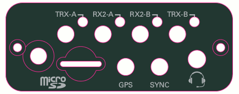
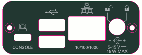
Like the USRP X300 and N310 series, E320 has connectors on both the front and back panel. The back panel holds the power connector, all network connections, USB connections for serial console (see Serial connection), JTAG and peripherals, and front-panel GPIO.
The front panel is used for all RF connections, SMA connectors for GPS antenna input, 10 MHz external clock reference.
The connectors are labeled RF A and RF B and are powered by the two channels of AD9361 RFIC.
Unlike the E31x, but like most other USRPs, the USRP E320 has separate inputs for clock and time reference. There is no separate internal 10 MHz oscillator, when selecting an 'internal' reference, the GPSDO is used to create reference signals.
To reduce phase noise, it may be necessary to power down the GPSDO when using an external reference. To do this, just add enable_gps=False to args when connecting to the radio. Note that adding enable_gps to args will override any enable_gps value in the E320's MPM configuration (see Configuration Files).
The values 'internal' and 'gpsdo' are thus interchangeable and mean the same thing.
| GPIO | Mini HDMI (Type C) | HDMI (Type A) |
|---|---|---|
| Data[0] | Data 0+ - Pin 8 | Pin 7 |
| Data[1] | Data 0- - Pin 9 | Pin 9 |
| Data[2] | Clock 0+ - Pin 11 | Pin 10 |
| Data[3] | Clock 0- - Pin 12 | Pin 12 |
| Data[4] | CEC - Pin 14 | Pin 13 |
| Data[5] | SCL - Pin 15 | Pin 15 |
| Data[6] | SDA - Pin 16 | Pin 16 |
| Data[7] | Utility - Pin 17 | Pin 14 |
EEPROM flags can be set with
$ eeprom-set-flags 0xFLAGS
where FLAGS is the hex number that you can construct with the following table of bits:
| Bit | Description |
|---|---|
| 0 | Auto-boot (1=on) |
| 1 | Fan (1=present) |
| 2 | TPM (0=present) |
| 3 | Enclosure (1=present) |
For example, to set your device to auto-boot, with TPM, and with fans, the flag value is 0x3, so
$ eeprom-set-flags 0x3
The enclosure flag is typically set during the manufacturing process, and can be used to identify if the board has an enclosure is used. The firmware and thermal subsystems of this device also use this flag to load different default thermal settings (see the SCU firmware code).
The following tables describe how FPGA registers are mapped into the PS. This is for reference only, most users will not even have to know about this table.
| AXI Slave | Address Range | UIO Label | Description |
|---|---|---|---|
| Slave 0 | 4000_0000 - 4000_3fff | - | Ethernet DMA SFP (only for E320) |
| Slave 1 | 4000_4000 - 4000_4fff | misc-enet-regs | Ethernet registers SFP (only for E320) |
| Slave 2 | 4001_0000 - 4001_3fff | mboard-regs | Motherboard control |
| Slave 3 | 4001_4000 - 4001_41ff | dboard-regs | Daughterboard control |
| AXI Slave | Module | Address | Name | Read/Write | Description |
|---|---|---|---|---|---|
| Slave 0 | axi_eth_dma | 4000_0000 - 4000_4fff | Ethernet DMA | RW | See Linux Driver (only on E320) |
| Slave 1 | e320_mgt_io_core | 4000_4000 | PORT_INFO | RO | SFP port information |
| [31:24] | COMPAT_NUM | RO | - | ||
| [23:18] | 6'h0 | RO | - | ||
| [17] | activity | RO | - | ||
| [16] | link_up | RO | - | ||
| [15:8] | mgt_protocol | RO | 0 - None, 1 - 1G, 2 - XG, 3 - Aurora | ||
| [7:0] | PORTNUM | RO | - | ||
| e320_mgt_io_core | 4000_4004 | MAC_CTRL_STATUS | RW | Control 10gE and Aurora mac | |
| [0] | ctrl_tx_enable (PROTOCOL = "10GbE") | RW | - | ||
| [0] | bist_checker_en (PROTOCOL = "Aurora") | RW | - | ||
| [1] | bist_gen_en | RW | - | ||
| [2] | bist_loopback_en | RW | - | ||
| [8:3] | bist_gen_rate | RW | - | ||
| [9] | phy_areset | RW | - | ||
| [10] | mac_clear | RW | - | ||
| e320_mgt_io_core | 4000_4008 | PHY_CTRL_STATUS | RW | Phy reset control | |
| e320_mgt_io_core | 4000_400C | MAC_LED_CTL | RW | Used by ethtool to indicate port | |
| [1] | identify_enable | RW | - | ||
| [0] | identify_value | RW | - | ||
| mdio_master | 4000_4010 | MDIO_DATA | RW | - | |
| 4000_4014 | MDIO_ADDR | RW | - | ||
| 4000_4018 | MDIO_OP | RW | - | ||
| 4000_401C | MDIO_CTRL_STATUS | RW | - | ||
| e320_mgt_io_core | 4000_4020 | AURORA_OVERUNS | RO | - | |
| 4000_4024 | AURORA_CHECKSUM_ERRORS | RO | - | ||
| 4000_4028 | AURORA_BIST_CHECKER_SAMPS | RO | - | ||
| 4000_402C | AURORA_BIST_CHECKER_ERRORS | RO | - | ||
| eth_switch | 4000_5000 | MAC_LSB | RW | Device MAC LSB | |
| 4000_5004 | MAC_MSB | RW | Device MAC MSB | ||
| 4000_6000 | IP | RW | Device IP | ||
| 4000_6004 | PORT1, PORT0 | RW | Device UDP port | ||
| eth_dispatch | 4000_6008 | [1] ndest, [0] bcast | RW | Enable Crossover | |
| 4000_600c | [1] my_icmp_type, [0] my_icmp_code | - | |||
| eth_switch | 4000_6010 | BRIDGE_MAC_LSB | Bridge SFP ports in ARM | ||
| 4000_6014 | BRIDGE_MAC_MSB | - | |||
| 4000_6018 | BRIDGE_IP | - | |||
| 4000_601c | BRIDGE_PORT1, BRIDGE_PORT0 | - | |||
| 4000_6020 | BRIDGE_EN | - | |||
| chdr_eth_framer | 4000_6108 onwards | LOCAL_DST_IP | W | Destination IP, MAC, UDP for Outgoing Packet for 256 SIDs | |
| 4000_6208 onwards | LOCAL_DST_UDP_MAC_MSB | W | Destination MAC for outgoing packets (MSB) | ||
| 4000_6308 onwards | LOCAL_DST_MAC_LSB | W | Destination MAC for outgoing packets (LSB) | ||
| 4000_7000 onwards | REMOTE_DST_IP | W | Destination IP, MAC, UDP for Outgoing Packet for 16 local addrs | ||
| 4000_7400 onwards | REMOTE_DST_UDP_MAC_HI | W | Destination MAC (MSB) | ||
| 4000_7800 onwards | REMOTE_DST_MAC_LO | W | Destination MAC (LSB) | ||
| Slave 2 | e3xx_core | 4001_0000 | COMPAT_NUM | R | FPGA Compat Number |
| [31:16] | Major | RO | - | ||
| [15:0] | Minor | RO | - | ||
| 4001_0004 | DATESTAMP | RO | - | ||
| 4001_0008 | GIT_HASH | RO | - | ||
| 4001_000C | SCRATCH | RO | - | ||
| 4001_0010 | REG_DEVICE_ID | RW | RFNoC Device ID | ||
| 4001_0014 | REG_RFNOC_INFO | RO | RFNoC Information | ||
| [31:16] | CHDR_W | RO | RFNoC CHDR Width in Bits | ||
| [15:0] | RFNOC_PROTOVER | RO | RFNoC Protocol Version | ||
| 4001_0018 | CLOCK_CTRL | - | |||
| [0] | pps select (internal 10 MHz) | RW | One-hot encoded pps_select to use the internal PPS from GPSDO | ||
| [1] | pps select (external 10 MHz) | RW | One-hot encoded pps_select to use the external PPS. | ||
| [2] | refclk_select (internal/external 10 MHz) | RW | refclk_select=0 for internal (GPSDO) 10 MHz, refclk_sel=1 for external 10 MHz. | ||
| 4001_001C | XADC_READBACK | RO | - | ||
| [11:0] | FPGA temperature | RO | - | ||
| 4001_0020 | BUS_CLK_RATE | RO | - | ||
| 4001_0024 | BUS_CLK_COUNT | RO | - | ||
| 4001_0028 | SFP_PORT_INFO | RO | Same as port_info register 0x4000_4000 | ||
| 4001_002C | FP_GPIO_CTRL | RW | - | ||
| 4001_0030 | FP_GPIO_MASTER | RW | GPIO master select bits. One bit per GPIO. LSB is for GPIO 0. Set bit to 0 for Radio, 1 for PS. | ||
| 4001_0034 | FP_GPIO_RADIO_SRC | RW | Radio channel source select bits. Two bits per GPIO. Bits [1:0] are for GPIO 0. Set to 00 for channel 0, 01 for channel 1, etc. | ||
| 4001_0038 | GPS_CTRL | RW | E320 Only | ||
| [0] | GPS_PWR_EN | RW | Power on GPSDO | ||
| [1] | GPS_RST_N | RW | - | ||
| [2] | GPS_INITSURV_N | RW | - | ||
| 4001_003C | GPS_STATUS | RO | GPSDO Status, E320 Only | ||
| [0] | GPS_LOCK | RO | Returns 1 if GPSDO is locked | ||
| [1] | GPS_ALARM | RO | - | ||
| [2] | GPS_PHASELOCK | RO | - | ||
| [3] | GPS_SURVEY | RO | - | ||
| [4] | GPS_WARMUP | RO | - | ||
| 4001_0040 | DBOARD_CTRL | RO | - | ||
| 4001_0044 | DBOARD_STATUS | RO | - | ||
| 4001_0048 | NUM_TIMEKEEPERS | RO | Number of radio timekeepers | ||
| Slave 4 | 4001_4000 | 4001_41FF | Daughterboard Registers | - | Don't exist now. TBD |
 1.8.17