|
USRP Hardware Driver and USRP Manual
Version: 4.9.0.0
UHD and USRP Manual
|


|
|
USRP Hardware Driver and USRP Manual
Version: 4.9.0.0
UHD and USRP Manual
|
|
More information:
This will run you through the first steps relevant to get your USRP X300/X310 up and running. Here, we assume you will connect your USRP using Gigabit Ethernet (1GigE), as this interface is readily available in most computers. For 10 Gigabit Ethernet (10GigE) or PCI Express (PCIe), see the corresponding sections in this manual page.
Before you can start using your USRP, you might have to assemble the hardware, if this has not yet happened. Make sure you are grounded (e.g. by touching a radiator) in order not to damage sensitive electronics through static discharge!
The next step is to make sure your computer can talk to the USRP. An otherwise unconfigured USRP device will have the IP address 192.168.10.2 when using 1GigE. It is recommended to directly connect your USRP to the computer at first, and to set the IP address on your machine to 192.168.10.1. See Setup the host interface on details how to change your machine's IP address.
Note: If you are running an automatic IP configuration service such as Network Manager, make sure it is either deactivated or configured to not change the network device! This can, in extreme cases, lead to you bricking the USRP!
If your network configuration is correct, running uhd_find_devices will find your USRP and print some information about it. You will also be able to ping the USRP by running:
ping 192.168.10.2
on the command line. At this point, you should also run:
uhd_usrp_probe --args addr=192.168.10.2
to make sure all of your components (daughterboards, GPSDO) are correctly detected and usable.
If the output from uhd_find_devices and uhd_usrp_probe didn't show any warnings, you can skip this step. However, if there were errors regarding the FPGA version compatibility number, you will have to update the FPGA image before you can start using your USRP.
uhd_images_downloader script provided with UHD (see also Firmware and FPGA Images).Use the uhd_image_loader utility to update the FPGA image. On the command line, run:
uhd_image_loader --args="type=x300,addr=192.168.10.2,fpga=HG"
If you have installed the images to a non-standard location, you might need to run (change the filename according to your device):
uhd_image_loader --args="type=x300,addr=192.168.10.2" --fpga-path="<path_to_images>/usrp_x310_fpga_HG.bit"
The process of updating the FPGA image will take several minutes. Make sure the process of flashing the image does not get interrupted.
See Load the Images onto the On-board Flash for more details.
When your FPGA is up to date, power-cycle the device and re-run uhd_usrp_probe. There should be no more warnings at this point, and all components should be correctly detected. Your USRP is now ready for development!
Like any other USRP, all X3X0 USRPs are controlled by the UHD software. To integrate a USRP X3X0 into your C++ application, you would generate a UHD device in the same way you would for any other USRP:
For a list of which arguments can be passed into make(), see Section Device arguments.
| Key | Description | Example Value |
|---|---|---|
| addr | IPv4 address of primary SFP+ port to connect to | addr=192.168.30.2 |
| second_addr | IPv4 address of secondary SFP+ port to connect to | second_addr=192.168.40.2 |
| resource | NI-RIO resource | resource=RIO0 |
| master_clock_rate | Master Clock Rate in Hz (see Motherboard clock) | master_clock_rate=184.32e6 |
| dboard_clock_rate | Daughterboard Clock Rate in Hz | dboard_clock_rate=50e6 |
| system_ref_rate | Frequency of external reference/clock signal in Hz (see Ref Clock (10 MHz or other frequency)) | system_ref_rate=30.72e6 |
| serialize_init | Force serial initialization of motherboards (default: initialize in parallel) | serialize_init=1 |
| time_source | Specify the time (PPS) source | time_source=external |
| clock_source | Specify the reference clock source | clock_source=external |
| self_cal_adc_delay | Run ADC transfer delay self-calibration routine | self_cal_adc_delay=1 |
| ext_adc_self_test | Run extended ADC self-test (excludes self_cal_adc_delay) | ext_adc_self_test=1 |
| ext_adc_self_test_duration | Duration of extended ADC self-test (default: 30s) | ext_adc_self_test_duration=60 |
| recover_mb_eeprom | Enable EEPROM recovery, disable HW revision checks (see Corrupt EEPROM) | recover_mb_eeprom=1 |
| use_dpdk | Use DPDK (see DPDK, Data Plane Development Kit) | use_dpdk=1 |
| fpga | Choose FPGA image to run (only works over PCIe) | fpga=/path/to/bitfile.lvbitx |
| fw | Load custom firmware image | fw=/path/to/hw.bin |
uhd_find_devices).Ettus Research recommends the Intel Ethernet Converged Network Adapter X520-DA2 interface for communication with the USRP X300/X310 device. Installation instructions for this interface are available on the official Intel website.
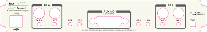
uhd_find_devices).The LEDs on the front panel can be useful in debugging hardware and software issues (see Front Panel)
In order to utilize the X-series USRP over dual 10 Gigabit Ethernet interfaces, ensure either the XG image is installed (see FPGA Image Flavors). In addition to burning the prerequisite FPGA image, it may also be necessary to tune the network interface card (NIC) to eliminate drops (Ds) and reduce overflows (Os). This is done by increasing the number of RX descriptors (see Linux specific notes).
The benchmark_rate tool can be used to test this capability. Run the following commands to test the X-series USRP over both 10 Gigabit Ethernet interfaces with the maximum rate of 200 Msps per channel:
cd <install-path>/lib/uhd/examples
./benchmark_rate --args="type=x300,addr=<Primary IP>,second_addr=<secondary IP>" --channels="0,1" --rx_rate 200e6
The second interface is specified by the extra argument second_addr.
To enable the highest streaming rates over the network, X310 supports using transports based on the Data Plane Development Kit (DPDK). See the DPDK page for details on how it can improve streaming and how to use it.
The USRP X300 and X310 support streaming data to a remote network destination. See Remote streaming for more details.
Important Note: The USRP X-Series provides PCIe connectivity over MXI cable. We will use the 'MXI' nomenclature for the rest of this manual.
In order to use the USRP X-Series on a PCIe-over-MXI connection, you need to install the NI RIO drivers on your system. Please follow the instructions here: NI RIO Kernel Modules for X-Series PCIe Connectivity
Follow the instructions listed in the Set Up Your MXI-Express x4 System document to setup the NI PCIe-8371 module.
Note: The USRP device is not hot-pluggable over PCI Express. Any connection changes with only be detected by your computer after a successful reboot.
Two possible failure modes are your computer not booting when connected to your USRP device through MXI-Express, and Windows not properly discovering your devices (for example, there is a yellow exclamation point on a PCI to PCI bridge in Windows Device Manager, despite drivers for all devices being installed). These situations often are due to programming errors in PCI Express device configuration of the BIOS. To use this software, you need a MXI-Express device that supports Mode 1 operation. Refer to NI MXI-Express BIOS Compatibility Software Readme for more information.
The BIOS Compatibility Software can be downloaded for Windows from the MXI-Express BIOS Compatibility Software page.
Important Note: The USRP X-Series provides PCIe connectivity over MXI cable We will use the 'MXI' nomenclature for the rest of this manual.
In order to use the USRP X-Series on a PCIe-over-MXI connection, you need to install the NI RIO drivers on your system. Please follow the instructions here: NI RIO Kernel Modules for X-Series PCIe Connectivity
Follow the instructions listed in the “Installing an NI ExpressCard-8360 Host Card” section of the Set Up Your MXI-Express x1 System document to setup the NI ExpressCard-8360B module.
Because a laptop computer is not grounded, follow this procedure to safely connect a laptop computer to your USRP device.
Note: The USRP device is not hot-pluggable over PCI Express. Any connection changes will only be detected by your computer after a successful reboot.
The USRP X3x0 includes an on-board JTAG programmer, built into the motherboard. To connect to this JTAG device, simply connect your computer to the USB JTAG port on the front of the X3x0 device. You may now use the JTAG programmer in the same way you would use any other, including:
In order to use the JTAG programmer with the Xilinx tools, the Digilent drivers and plugin have to be installed first. Although recent versions of Vivado ship with the driver, it has to still be manually installed.
To install first locate your Vivado installation path on a Linux system (default is /opt/Xilinx/Vivado/<Version>):
sudo `find /opt/Xilinx/Vivado/<Version> -name install_digilent.sh`
The USRP-X series device should now be usable with all the tools mentioned above.
The USRP-X Series device ships with a bitstream pre-programmed in the flash, which is automatically loaded onto the FPGA during device power-up. However, a new FPGA image can be configured over the PCI Express interface or the on-board USB-JTAG programmer. This process can be seen as a "one-time load", in that if you power-cycle the device, it will not retain the FPGA image.
Please note that this process is different than replacing the FPGA image stored in the flash, which will then be automatically loaded the next time the device is reset.
The USRP-X Series devices contains two SFP+ ports for the two Ethernet channels. Because the SFP+ ports support both 1 Gigabit (SFP) and 10 Gigabit (SFP+) transceivers, several FPGA images are shipped with UHD to determine the behavior of the above interfaces.
| FPGA Image Flavor | SFP+ Port 0 Interface | SFP+ Port 1 Interface |
|---|---|---|
| HG (Default) | 1 Gigabit Ethernet | 10 Gigabit Ethernet |
| XG | 10 Gigabit Ethernet | 10 Gigabit Ethernet |
| HA | 1 Gigabit Ethernet | Aurora |
| XA | 10 Gigabit Ethernet | Aurora |
Note: The Aurora images need to be built manually from the FPGA source code.
FPGA images are shipped in 2 formats:
To get the latest images, simply use the uhd_images_downloader script. On Unix systems, use this command:
$ [sudo] uhd_images_downloader
On Windows, use:
<path_to_python.exe> <install-path>/bin/uhd_images_downloader.py
UHD requires a valid LabVIEW FPGA configuration bitstream file (LVBITX) to use the USRP-X Series device over the PCI Express bus. LabVIEW FPGA is not required to use UHD with a USRP-X Series device. Because FPGA configuration is a part of normal operation over PCI Express, there is no setup required before running UHD.
The fpga tag can be set in the optional device args passed to indicate the FPGA image flavor to UHD. If the above tag is specified, UHD will attempt to load the FPGA image with the requested flavor from the UHD images directory. If the tag is not specified, UHD will automatically detect the flavor of the image and attempt to load the corresponding configuration bitstream onto the device. Note that if UHD detects that the requested image is already loaded onto the FPGA then it will not reload it.
The USRP-X Series device features an on-board USB-JTAG programmer that can be accessed on the front-panel of the device. There are multiple tools available to access the FPGA through the JTAG connector (see On-Board JTAG Programmer).
If you have Vivado installed, we provide a command-line script to flash images. Make sure your X3x0 is powered on and connected to your computer using the front panel USB JTAG connector (USB 2.0 is fine for this). Head to the X3x0 FPGA directory, then run the following commands:
$ cd uhd/fpga/usrp3/top/x300 # Assuming this is where the FPGA code is checked out
$ source ./setupenv.sh
$ viv_jtag_program /path/to/bitfile.bit
If you have iMPACT installed, you can use the impact_jtag_programmer.sh tool to install images. Then run the tool:
<path_to_uhd_tools>/impact_jtag_programmer.sh --fpga-path=<fpga_image_path>
To change the FPGA image stored in the on-board flash, the USRP-X Series device can be reprogrammed over the network or PCI Express. Once you have programmed an image into the flash, that image will be automatically loaded on the FPGA during the device boot-up sequence.
Note: Different hardware revisions require different FPGA images. Determine the revision number from the sticker on the rear of the device. If you are manually specifying an FPGA path, the utility will not try to detect your device information, and you will need to use this number to select which image to burn.
Note: The image loader utility will default to using the appropriate BIT file if no custom FPGA image path is specified, but it is compatible with BIN, BIT, and LVBITX images.
Automatic FPGA path, detect image type:
uhd_image_loader --args="type=x300,addr=<IP address>"

Automatic FPGA path, select image type:
uhd_image_loader --args="type=x300,addr=<IP address>,fpga=<HG or XG>"

Manual FPGA path:
uhd_image_loader --args="type=x300,addr=<IP address>" --fpga-path="<path to FPGA image>"
Automatic FPGA path, detect image type:
uhd_image_loader --args="type=x300,resource=<NI-RIO resource>"

Automatic FPGA path, select image type:
uhd_image_loader --args="type=x300,resource=<NI-RIO resource>,fpga=<HG or XG>"

Manual FPGA path:
uhd_image_loader --args="type=x300,resource=<NI-RIO resource>" --fpga-path="<path to FPGA image>"
It is possible to put the device into an unusable state by loading bad images ("bricking"). Fortunately, the USRP-X Series device can be loaded with a good image temporarily using the USB-JTAG interface. Once booted into the safe image, the user can once again load images onto the device over Ethernet or PCI Express.
See Section Use JTAG to load FPGA images on how to load the FPGA image onto the device using a JTAG interface. After running the JTAG process, a new image can be flashed onto the device using the usual procedure to permently recover the device.
The USRP-X Series only supports Gigabit and Ten Gigabit Ethernet and will not work with a 10/100 Mbps interface.
Please note that 10 Gigabit Ethernet defines the protocol, not necessary the medium. For example, you may use 10GigE over optical with optical SFP+ transceiver modules.
The USRP-X Series communicates at the IP/UDP layer over the Gigabit and Ten Gigabit Ethernet. The default IP address for the USRP X300/X310 device depends on the Ethernet Port and interface used. You must configure the host Ethernet interface with a static IP address on the same subnet as the connected device to enable communication, as shown in the following table:
| Ethernet Interface | USRP Ethernet Port | Default USRP IP Address | Host Static IP Address | Host Static Subnet Mask | Address EEPROM key |
|---|---|---|---|---|---|
| Gigabit | Port 0 (HG Image) | 192.168.10.2 | 192.168.10.1 | 255.255.255.0 | ip-addr0 |
| Ten Gigabit | Port 0 (XG Image) | 192.168.30.2 | 192.168.30.1 | 255.255.255.0 | ip-addr2 |
| Ten Gigabit | Port 1 (HG/XG Image) | 192.168.40.2 | 192.168.40.1 | 255.255.255.0 | ip-addr3 |
As you can see, the X300/X310 actually stores different IP addresses, which all address the device differently: Each combination of Ethernet port and interface type (i.e., Gigabit or Ten Gigabit) has its own IP address. As an example, when addressing the device through 1 Gigabit Ethernet on its first port (Port 0), the relevant IP address is the one stored in the EEPROM with key ip-addr0, or 192.168.10.2 by default.
See Configuring the host's IP address on details how to change your machine's IP address and MTU size to work well with the X300.
For maximum throughput, one Ethernet interface per USRP is recommended, although multiple devices may be connected via an Ethernet switch. In any case, each Ethernet interface should have its own subnet, and the corresponding USRP device should be assigned an address in that subnet. Example:
192.168.10.1255.255.255.0192.168.10.2192.168.110.1255.255.255.0192.168.110.2If all devices are to be used in a compound, see also Multiple USRP configurations.
You may need to change the USRP's IP address for several reasons:
To change the USRP's IP address, you must know the current address of the USRP, and the network must be setup properly as described above. You must also know which IP address of the X300 you want to change, as identified by their address EEPROM key (e.g. ip-addr0, see the table above). Run the following commands:
UNIX:
cd <install-path>/lib/uhd/utils
./usrp_burn_mb_eeprom --args=<optional device args> --values="ip-addr0=192.168.10.3"
Windows:
cd <install-path>\lib\uhd\utils
usrp_burn_mb_eeprom.exe --args=<optional device args> --values="ip-addr0=192.168.10.3"
You must power-cycle the device before you can use this new address.
The X300 series generates a master clock on the motherboard, which is then used to drive the ADCs, DACs, and the radio blocks. This clock rate is referred to as the "master clock rate". There is always a single master clock rate per motherboard. This rate is also the base sample rate of the radio blocks. By using DDC and DUC blocks (these are part of the default X300/X310 FPGA image), the actual sampling rate available to your application can be an integer divisor of the master clock rate, so for a 200 MHz master clock rate, the sampling rate available to the application can be 200 Msps, 100 Msps, 66.6 Msps, 50 Msps, and so on.
The X300 series support a 200 MHz and a 184.32 MHz master clock rate, with 200 MHz being the default (when using TwinRX, only 200 MHz is available). To specify a master clock rate, use the master_clock_rate device arg at initialization time. Example:
Note: The X300 series does not support the uhd::usrp::multi_usrp::set_master_clock_rate() API call, because it can only configure the clock at initialization time, but not afterwards. To switch the master clock rate, destroy your USRP object, and recreate a new one. Example:
Due to the contract of uhd::usrp::multi_usrp::set_master_clock_rate(), the call will not throw an exception, but will coerce to the previously set master clock rate. Effectively, it will do nothing but print a warning (but it won't terminate your application). Also note that the return value of said API call as well as the associated getter will always return accurate values. Example:
The X3x0 provides a clock signal to the daughterboards which is used as a reference clock for synthesizers and other components that require clocks. There are daughterboards that require non-default clock values. See Section Device Configuration through address string on how to change the clock value, and Daughterboards for information specific to certain daughterboards.
Not all combinations of daughterboards work within the same device, if daughterboard clock requirements conflict. Note that some daughterboards will try and set the daughterboard clock rate themselves. Refer to the Ettus Research Knowledge Base article on the X300/X310 for more information on daughterboard compatibilty.
In a single-device configuration, the USRP device must have a unique IPv4 address on the host computer. The USRP can be identified through its IPv4 address, resolvable hostname, NI-RIO resource name or by other means. See the application notes on Device Identification. Use this addressing scheme with the uhd::usrp::multi_usrp interface (not a typo!).
Example device address string representation for a USRP-X Series device with IPv4 address 192.168.10.2:
addr=192.168.10.2
Example device address string representation for a USRP-X Series device with RIO resource name RIO0 over PCI Express:
resource=RIO0
In a multi-device configuration, each USRP device must have a unique IPv4 address on the host computer. The device address parameter keys must be suffixed with the device index. Each parameter key should be of the format <key><index>. Use this addressing scheme with the uhd::usrp::multi_usrp interface.
Example device address string representation for 2 USRPs with IPv4 addresses 192.168.10.2 and 192.168.20.2:
addr0=192.168.10.2, addr1=192.168.20.2
See also Multiple USRP configurations.
When setting up a development machine for the first time, you may have various difficulties communicating with the USRP device. The following tips are designed to help narrow down and diagnose the problem.
This is a common error that occurs when you have set the subnet of your network interface to a different subnet than the network interface of the USRP device. For example, if your network interface is set to 192.168.20.1, and the USRP device is 192.168.10.2 (note the difference in the third numbers of the IP addresses), you will likely see a 'no control response' error message.
Fixing this is simple - just set the your host PC's IP address to the same subnet as that of your USRP device. Instructions for setting your IP address are in the previous section of this documentation.
When the IP address is not specified, the device discovery broadcasts UDP packets from each Ethernet interface. Many firewalls will block the replies to these broadcast packets. If disabling your system's firewall or specifying the IP address yields a discovered device, then your firewall may be blocking replies to UDP broadcast packets. If this is the case, we recommend that you disable the firewall or create a rule to allow all incoming packets with UDP source port 49152.
The USRP device will reply to ICMP echo requests ("ping"). A successful ping response means that the device has booted properly and that it is using the expected IP address.
ping 192.168.10.2
UHD requires the RIO device manager service to be running in order to communicate with an X-Series USRP over PCIe. This service is installed as a part of the USRP RIO (or NI-USRP) installer. On Linux, the service is not started at system boot time, and is left to the user to control. To start it, run the following command:
sudo niusrprio_pcie start
If the device still does not enumerate after starting the device manager, make sure that the host computer has successfully detected it. You can do so by running the following command:
lspci -k -d 1093:c4c4
A device similar to the following should be detected:
$ lspci -k -d 1093:c4c4
04:00.0 Signal processing controller: National Instruments ...
       Subsystem: National Instruments Device 76ca
       Kernel driver in use: niusrpriok_shipped
UHD requires the RIO device manager service to be running in order to communicate with an X-Series USRP over PCIe. This service is installed as a part of the USRP RIO (or NI-USRP) installer. On Windows, it can be found in the Services section in the Control Panel and it is started at system boot time. To ensure that the service is indeed started, navigate to the Services tag in the Windows Task Manager and ensure that the status of niusrpriorpc is "Running".
If the device still does not enumerate after starting the device manager, make sure that the host computer has successfully detected it. You can do so by checking if your device shows up in the Windows Device Manager.
Use Wireshark to monitor packets sent to and received from the device.
When there is network traffic arriving at the Ethernet port, LEDs will light up. You can use this to make sure the network connection is correctly set up, e.g. by pinging the USRP and making sure the LEDs start to blink.
This is a rare bug in which the X-Series device's on-board EEPROM becomes corrupt and reports an incorrect firmware and FPGA version. In this situation, UHD cannot properly use the device. To fix this bug, use the usrp_burn_mb_eeprom utility as follows:
usrp_burn_mb_eeprom --args="type=x300,recover_mb_eeprom,disable_adc_self_test" --values="revision=(NUM HERE)"
Afterward, power-cycle your X-Series device for the changes to take effect.
Using an external 10 MHz reference clock, a square wave will offer the best phase noise performance, but a sinusoid is acceptable. The power level of the reference clock must not exceed +15 dBm.
The following reference frequencies are supported:
If the external reference clock is not 10 MHz, the system_ref_rate device arg must be provided.
To use the external reference in your UHD session, make sure to either call uhd::usrp::multi_usrp::set_clock_source() or specify clock_source=external in your device args.
Using a PPS signal for timestamp synchronization requires a square wave signal with a 5Vpp amplitude.
To test the PPS input, you can use the following tool from the UHD examples:
<args> are device address arguments (optional if only one USRP device is on your machine)
cd <install-path>/lib/uhd/examples ./test_pps_input –args=<args>
To use the external time source in your UHD session, make sure to either call uhd::usrp::multi_usrp::set_time_source() or specify time_source=external in your device args.
Please see Internal GPSDO Application Notes (USRP-X3x0 Models) for information on configuring and using the internal GPSDO.
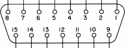
The GPIO port is not meant to drive big loads. You should not try to source more than 5mA per pin.
The +3.3V is for ESD clamping purposes only and not designed to deliver high currents.
Please see the GPIO API for information on configuring and using the GPIO bus.
| LED | Description | |
|---|---|---|
| DS1 | 1.2V | power |
| DS2 | TXRX1 | Red: TX, Green: RX |
| DS3 | RX1 | Green: RX |
| DS4 | REF | reference lock |
| DS5 | PPS | flashes on edge |
| DS6 | GPS | GPS lock |
| DS7 | SFP0 | link |
| DS8 | SFP0 | link activity |
| DS10 | TXRX2 | Red: TX Green: RX |
| DS11 | RX2 | Green: RX |
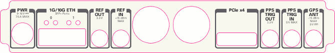
| DS12 | 6V | daughterboard power |
| DS13 | 3.8V | power |
| DS14 | 3.3V | management power |
| DS15 | 3.3V | auxiliary management power |
| DS16 | 1.8V | FPGA power |
| DS16 | 3.3V | FPGA power |
| DS19 | SFP1 | link |
| DS20 | SFP1 | link active |
| DS21 | LINK | link activity |
Xilinx chipscope allows for debugging custom FPGA designs similar to a logic analyzer. USRP-X series devices can be used with Xilinx chipscope using the onboard USB JTAG connector.
Further information on how to use Chipscope can be found in the Xilinx Chipscope Pro Software and Cores User Guide (UG029).
The X300 series support the UHD power calibration API (see: Power Level Controls). Calibration data is daughterboard-specific, i.e., the daughterboard serial is used to map calibration data to a serial.
Daughterboards have to be manually calibrated using a calibrated power meter or signal generator.
During runtime, the device can be configured in several different ways.
The following pages may shed some light:
There are two complete DDC and DUC DSP chains in the FPGA. In the single channel case, only one chain is ever used. To receive from both channels, the user must set the RX or TX subdevice specification.
In the following example, a TVRX2 is installed. Channel 0 is sourced from subdevice RX1, and channel 1 is sourced from subdevice RX2 (RX1 and RX2 are antenna connectors on the TVRX2 daughterboard).
The following sensors are available for the USRP-X Series motherboards; they can be queried through the API.
When issuing multiple timed commands to an x3xx device, it is important to ensure that the device is streaming data in some capacity. In the HG and XG images, the DDC & DUC derive their sense of time from the header of passing packets. This sense of time is necessary to execute timed commands. Repeatedly issuing timed commands without streaming will result in the command queue of the DDC / DUC backing up and overflowing, putting the device in a state where a full restart is required.
 1.8.17