 |
USRP Hardware Driver and Device Manual
Version: 4.11.0.0-0-g0d7ed3b1
UHD and USRP Manual
|


|
|
USRP Hardware Driver and Device Manual
Version: 4.11.0.0-0-g0d7ed3b1
UHD and USRP Manual
|
|
The B310 has three variants: PCIe, OEM PCIe, and Enclosed Thunderbolt™.
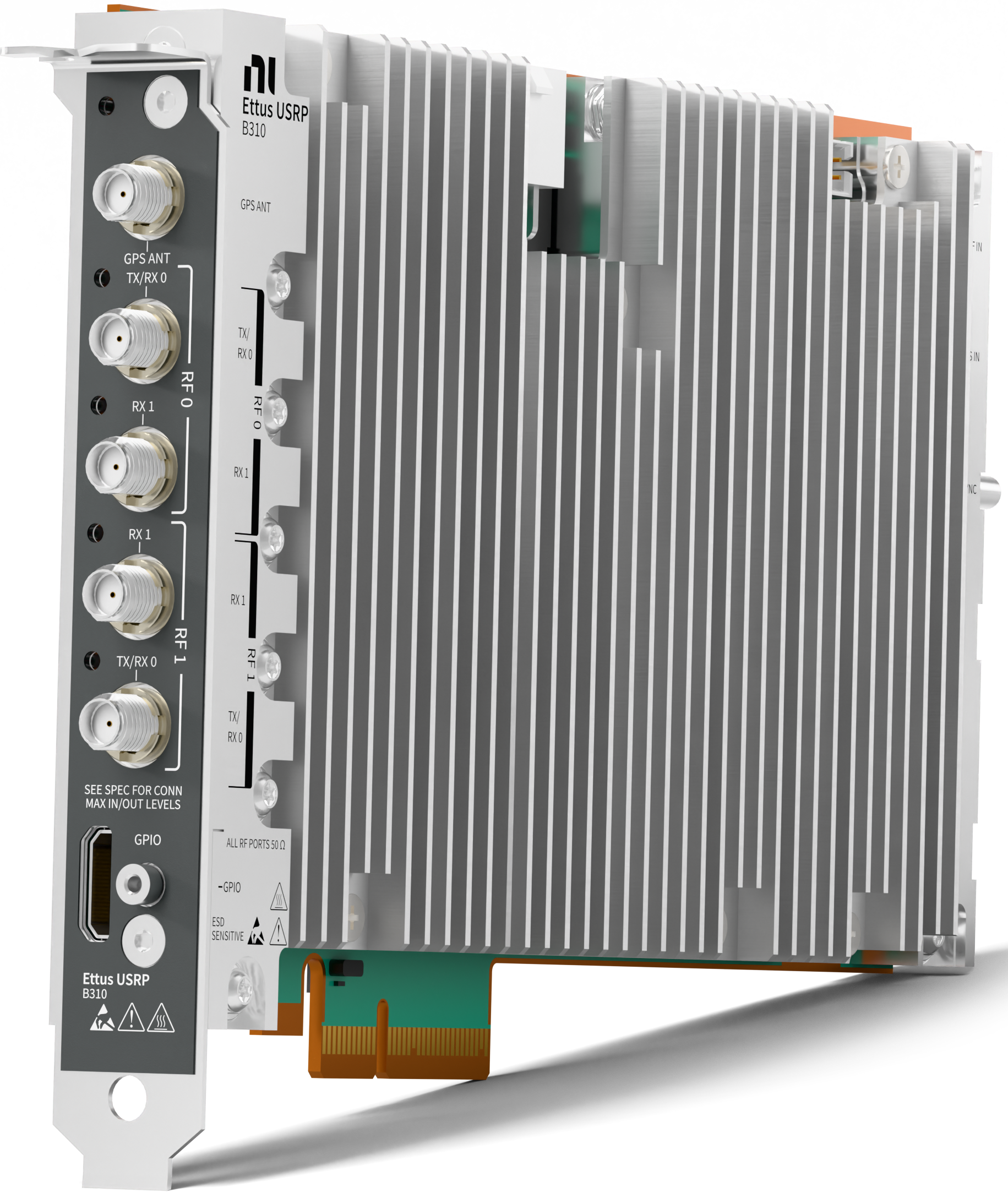
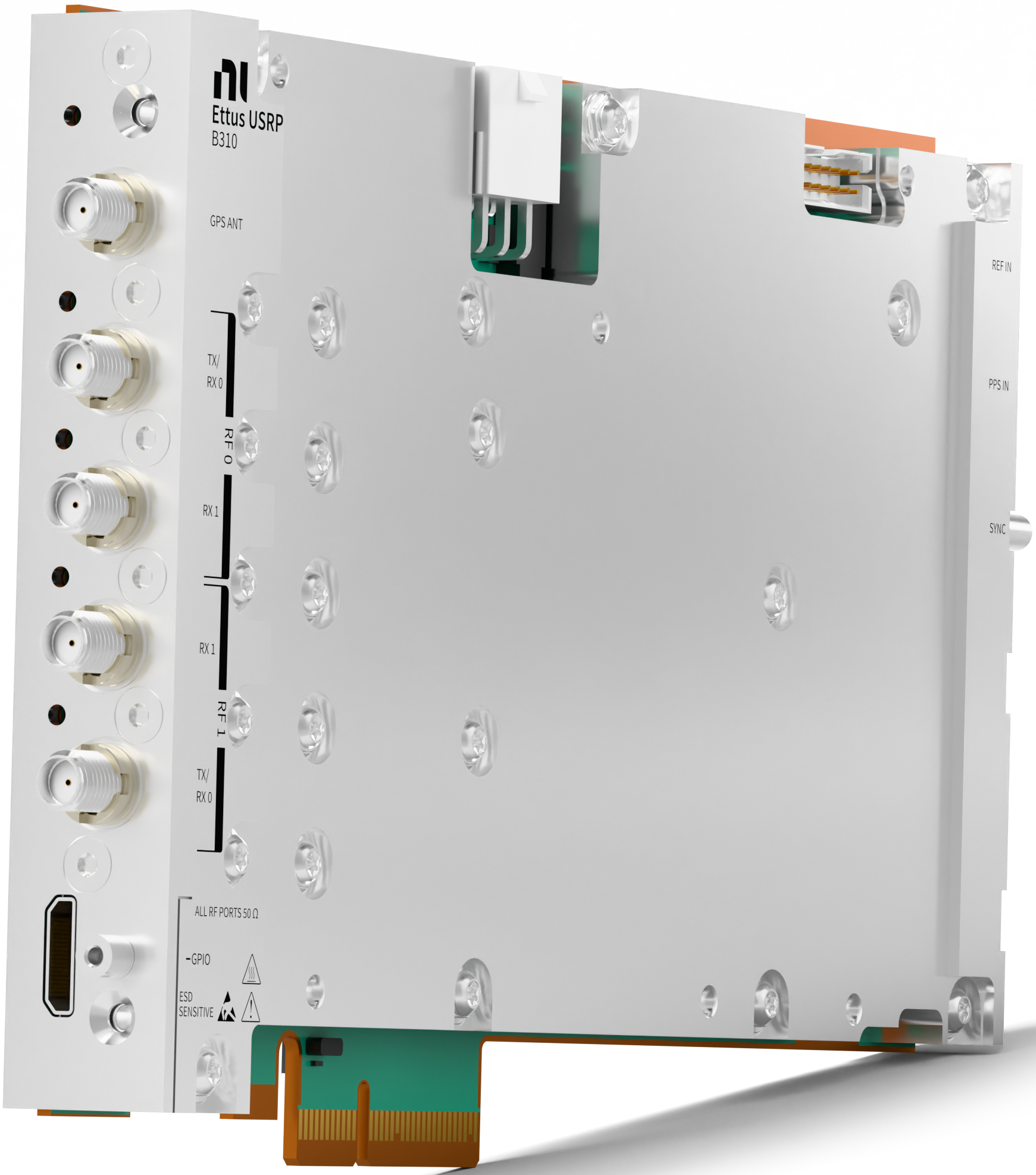
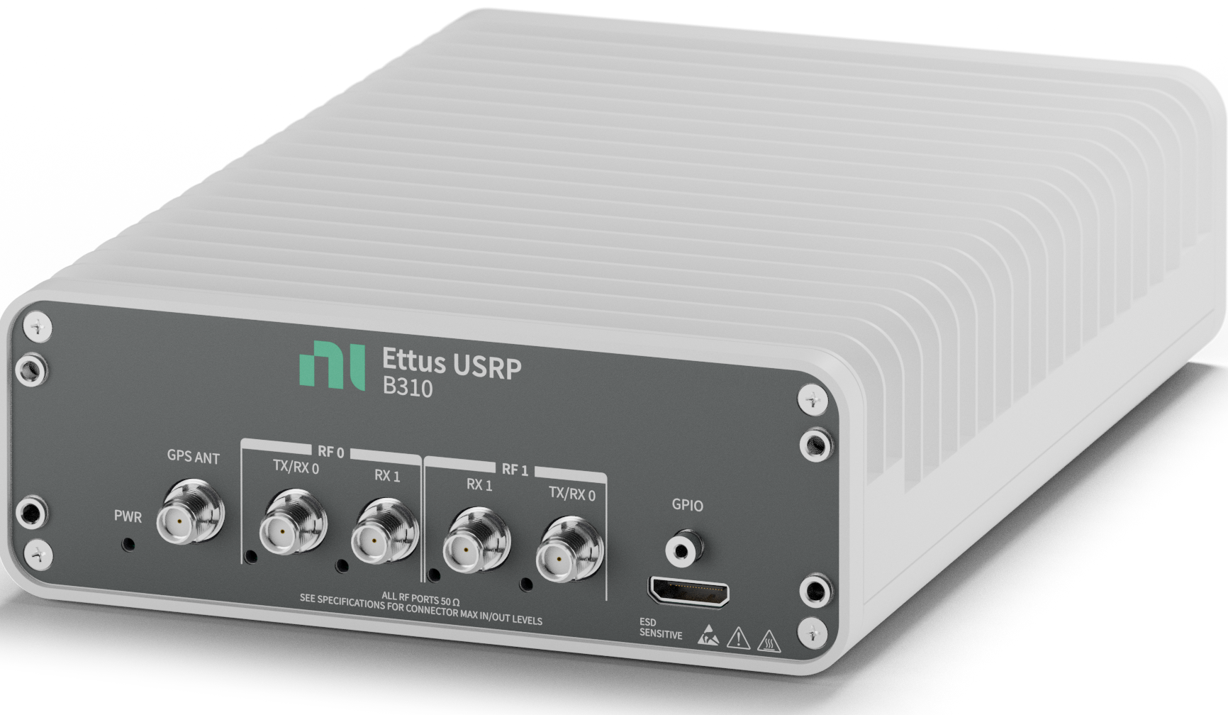
The Ettus USRP B310 is a B-Series USRP. All three variants utilize the same ADRV9032R transceiver as well as the same clocking circuitry. The PCIe variant is a superset of the OEM variant, including a PCIe front panel bracket and attached heatsink. Apart from the different mechanical enclosure, the Thunderbolt™ variant differs only by the added Thunderbolt™ circuitry to connect the module over Thunderbolt™ rather than PCIe card edge. The other pieces of the board are equivalent. The software support within UHD is the same for all three variants.
The front and back panels are equivalent between the three variants as far as ports are concerned. The only difference being that the Thunderbolt™ panels have a horizontal orientation, and the other variants have a vertical orientation. The below pictures are from the Thunderbolt™ variant.
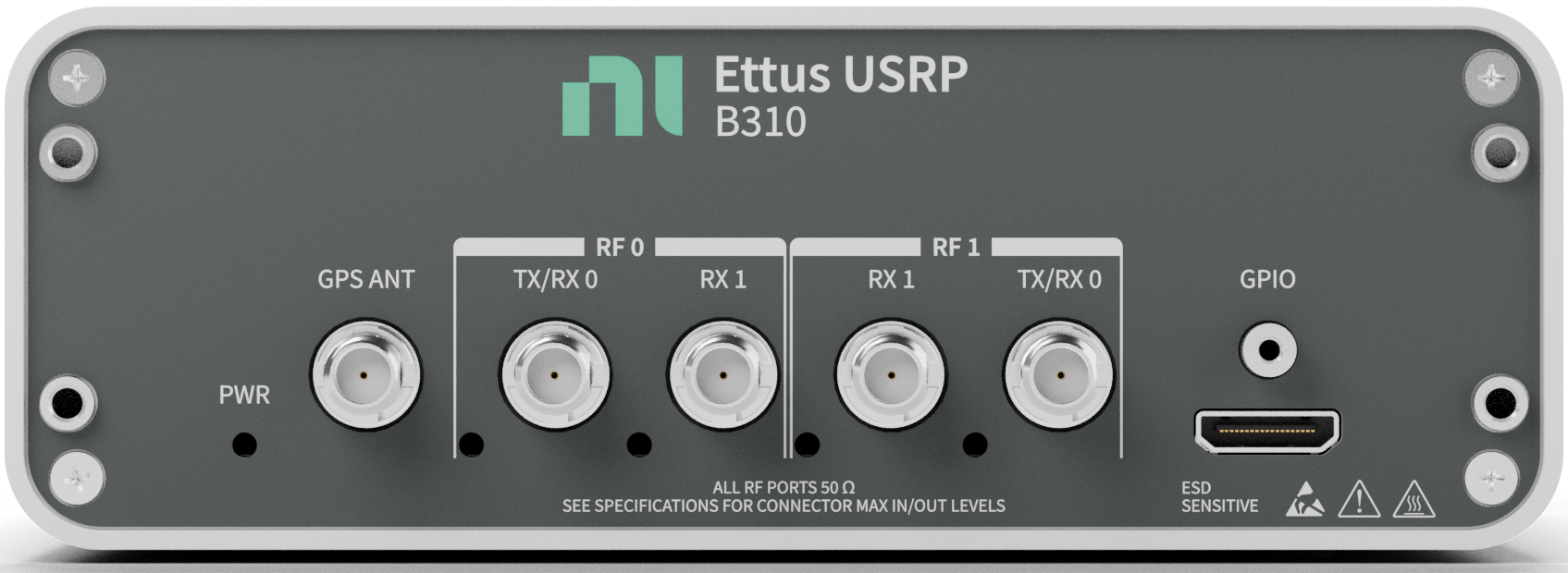
The B310 front panel provides access to the RF ports and status LEDs for each channel. It also provides access to the GPS antenna port and the Mini HDMI GPIO port. There is also a power LED status indicator.
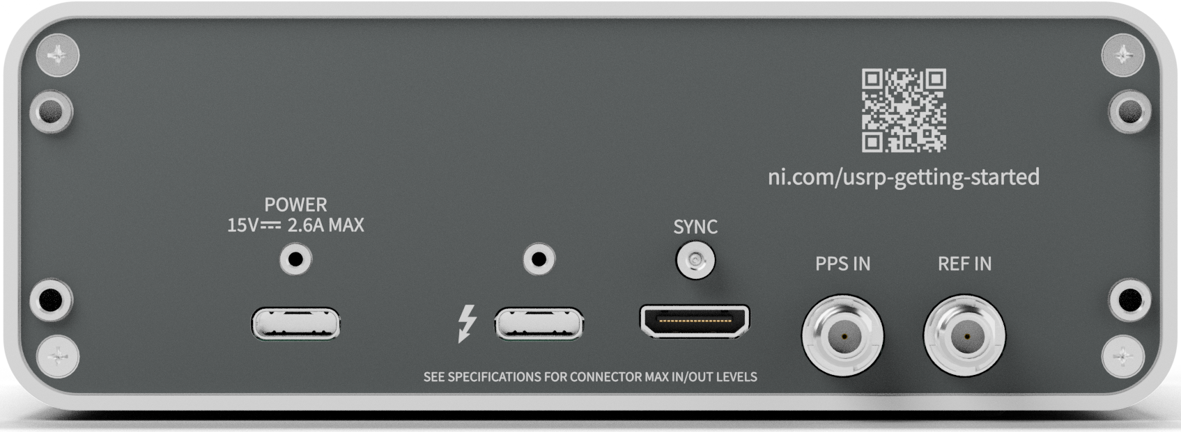
The B310 back panel provides access to the Reference and PPS In ports for clocking as well as the SYNC port that outputs the high-frequency reference and PPS out signals through use of the multi-device sync cable. The panel also provides access to the external power USB-C port and Thunderbolt™ USB-C port. These ports are only used in the Thunderbolt™ configuration but are present in the other configurations.
This section walks through the first steps to get your USRP B310 up and running. The B310 connects to your host computer via PCIe card edge or Thunderbolt™ depending on the variant.
The B310 requires the nib310rio kernel module on Linux, or the b310k driver on Windows. Without this kernel driver, UHD will not be able to detect or interact with the device.
To install either of these drivers, please follow the instructions here: B3xx Kernel Module Installation and Usage
See Driver not loaded for driver troubleshooting steps.
All Ettus Research products are individually tested before shipment. The USRP is guaranteed to be functional at the time it is received by the customer. Improper use or handling can cause the device to become non-functional. Take the following precautions to prevent damage:
Note: Use a certified Thunderbolt™ cable — not all cables with USB-C connectors support Thunderbolt™. Similarly, ensure the host port is Thunderbolt™-capable; not all USB-C ports support Thunderbolt™.
Once the driver is installed and the device is connected, run:
uhd_find_devices --args type=b3xx
to verify UHD can see the device. To probe all hardware components, run:
uhd_usrp_probe --args type=b3xx
Upon first use, update the FPGA image to the version of UHD you are utilizing to ensure compatibility between the driver and FPGA.
uhd_images_downloader script (see also Firmware and FPGA Images).uhd_image_loader to update the FPGA: uhd_image_loader --args="type=b3xx,resource=<resource>"
The B310 has two FPGA images that are shipped with UHD. The default FPGA, replay, has a RFNoC Replay block that can be used as with other RFNoC devices. The other FPGA, fifo, instead utilizes the DRAM as a buffer for improved streaming performance for the Thunderbolt™ variant.
To load a specific FPGA flavor, add the fpga device argument to the uhd_image_loader utility:
uhd_image_loader --args="type=b3xx,resource=<resource>,fpga=fifo"
If no FPGA flavor is specified, the default flavor will be programmed.
Utilization statistics are subject to change between UHD releases. This information is current as of UHD 4.11 and was taken directly from Xilinx Vivado 2021.1, targeting FPGA xc7k325t-fbg676-1.
The following table includes resource utilization for the replay FPGA bitfile.
The following table includes resource utilization for the fifo FPGA bitfile.
The ADRV9032R has several binaries that must be programmed every UHD session. To acquire these binaries, the user can run the following command:
uhd_images_downloader --types b3xx
The files should be present in the directory pointed to by UHD_IMAGES_DIR or the default UHD images location.
Like any other USRP, the B310 is controlled by the UHD software. To create a device handle in C++:
| Key | Description | Example Value |
|---|---|---|
| type | Device type filter | type=b3xx |
| resource | PCIe resource identifier | resource=nib310rio0 |
| master_clock_rate | Master clock rate used by the device (default: 122.88e6) | master_clock_rate=122.88e6 |
| system_ref_rate | External reference clock frequency in Hz (default: 10e6) | system_ref_rate=10e6 |
| clock_source | Reference clock source (see Setup Clocking) | clock_source=internal |
| time_source | Time/PPS source (see Setup Clocking) | time_source=internal |
| init_cals | ADRV9032 initialization calibration selection | init_cals=DEFAULT |
| tracking_cals | ADRV9032 tracking calibration selection | tracking_cals=DEFAULT |
The B310 supports master clock rates of 122.88MHz and 125MHz. This rate cannot be changed at runtime.
The following clock sources and time sources are available:
| Clock Source | Description |
|---|---|
internal | Internal clocking chip, default |
external | External reference input (10 MHz, 122.88 MHz, or 125 MHz) |
gpsdo | Internal clocking chip disciplined by onboard GPS chip |
sync | High-frequency sync signal from sync cable (rate = master clock rate) |
sync_gpsdo | GPSDO-disciplined sync signal from sync cable (rate = master clock rate) |
| Time Source | Description |
|---|---|
internal | Internal free-running timekeeper, default |
external | External PPS signal |
gpsdo | Timepulse from GPS chip |
sync | External PPS signal (meant for input via multi-device sync cable) |
sync_gpsdo | External PPS signal (meant for input via multi-device sync cable) |
Valid clock/time source combinations:
| Clock Source | Time Source |
|---|---|
internal | internal |
external | internal |
external | external |
external | sync |
external | sync_gpsdo |
gpsdo | gpsdo |
sync | sync |
sync_gpsdo | sync_gpsdo |
If the external reference clock is not 10 MHz, provide the system_ref_rate device arg. If using the sync, or sync_gpsdo clock source, you do not need to provide the system_ref_rate device arg, since it will be the rate of the master_clock_rate
To use an external reference:
Multiple B310 devices can be synchronized using a shared external clock and PPS signal. Connect each device to either the same 10 MHz reference and PPS source or via multi-device sync cable. Then, use clock_source=external and time_source=external if using a shared 10 MHz reference or clock_source=sync and time_source=sync if using the multi-device sync cable.
When all devices are configured with matching sync sources, the multi-device session will run the synchronization procedure automatically during initialization (resource names for the devices can be found via uhd_find_devices):
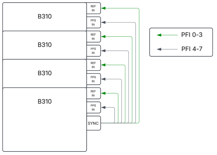
This procedure must be run during initialization for the ADRV9032 transceiver chips to synchronize correctly. The cabling for the multi-device system must be connected before the session is initialized. For the 10MHz external reference clock, the setup is similar to other USRPs and is documented here: External PPS and 10 MHz reference signals. For USRP B310, a new method of synchronization was introduced using the SYNC port on the back of USRP B310 and a separate multi-device sync cable. The multi-device sync cable is a mini HDMI to eight SMA cable, four of those SMAs (PFI 0-3) carry a high-frequency reference clock (either 122.88MHz or 125MHz, depending on the session master clock rate) and the other four SMAs (PFI 4-7) carry a PPS signal exported from the B310 that is connected to the SYNC port. This can be used to synchronize up four B310s. Any of the four B310s can be used for the mini HDMI connection, but this connection must be setup before the UHD session is opened. A diagram can be seen below for connecting four B310s using the multi-device sync cable. NI recommends using the accessory '791010-01 - USRP MULTI DEVICE DIRECT SYNC CABLE, 0.3M', orderable through ni.com or your local sales representative. This cable breaks out the mini-HDMI (HDMI Type C) to 8x SMA.
On Linux, UHD locates devices by scanning /sys/bus/pci/drivers/nib310rio/. The device resource key is the sysfs device identifier (e.g., an entry under the nib310rio subdirectory).
On Windows, UHD uses the Windows Device Manager to enumerate b310k driver devices and derives the resource from the PCIe bus:device:function location.
Typical UHD device address:
type=b3xx,resource=<resource string>
Multiple B310 devices may be used simultaneously by specifying each device's resource. Use the uhd::usrp::multi_usrp interface with a combined device resource args:
type=b3xx,resource0=<resource string for device 0>,resource1=<resource string for device 1>
For multi-device synchronization, ensure all devices share an external clock and PPS signal (see Multi-Device Synchronization).
The B310 uses an Analog Devices ADRV9032 transceiver.
TX/RX0TX/RX0, RX1Each channel has two LOs that can be set:
| LO Name | Sources | Description |
|---|---|---|
RFLO | LO0, LO1 | RF local oscillator from ADRV9032 synthesizer |
NCO | NCO | Numerically-controlled frequency shifter |
Since there are only two RFLOs and four channels, that means that channels will need to share RFLOs. By default, the two Rx channels share one LO, while the two Tx channels share the other LO. This means when you change the frequency of one channel, you will likely change the frequency of another.
Set the LO source using uhd::usrp::multi_usrp::set_rx_lo_source() or uhd::usrp::multi_usrp::set_tx_lo_source() with LO name "RFLO".
The ADRV9032 transceiver has built-in calibrations which can be enabled from UHD. A more detailed description of the calibrations can be found in the ADRV903x user guide, see section "ARM PROCESSOR AND DEVICE CALIBRATIONS".
Not all calibrations available on the ADRV9032R are applicable to the USRP B310. However, those calibrations that are applicable can be enabled/disabled at initialization time using the tracking_cals and init_cals device args (see also Device arguments). These can be set by using the following descriptive keys provided by UHD (e.g. init_cals=DEFAULT,tracking_cals=TX_QEC|RX_QEC). The | symbol can be used to combine keys (equivalent to a bitwise OR).
Calibrations can significantly delay the initialization of a session. By only picking relevant calibrations, sessions can be initialized faster.
Key (init_cal) | Function |
|---|---|
| RX_DC_OFFSET | Corrects for DC Offset within the receiver chain |
| ADC_RX | Calibrates the receiver ADC |
| ADC_ORX | Calibrates the observation receiver ADC |
| ADC_TXLB | Calibrates the Tx loopback receiver ADC |
| TXDAC | Calibrates the transmitter DAC |
| TXBBF | Tunes the corner frequency of the transmitter filter |
| TXLB_FILTER | Tx Loopback filter calibration |
| TXLB_PATH_DLY | Computes the transmitter to internal loopback path delay, which is required for the TxQEC initial calibration and tracking |
| TX_ATTEN_CAL | Tx atten phase/gain calibration |
| HRM | Performs HRM (harmonic reject mixer) harmonics rejection corrections |
| TXQEC | Performs an initial QEC calibration for the transmitter path. It utilizes the transmitter path and an internal loopback path |
| TXLOL | Performs an initial LO leakage calibration for the transmitter path. Utilizes the transmitter path and the internal loopback path |
Key (tracking_cal) | Function |
|---|---|
| RX_QEC | RxQEC Tracking calibration |
| RX_ADC | Rx ADC Tracking calibration |
| RXSPUR | RxSpur Tracking calibration |
| TX_QEC | TxQEC Tracking calibration |
| TX_LB_ADC | TxLB ADC Tracking calibration |
If Tx QEC tracking calibrations are active, there are ranges of frequency that must be avoided due to being within 1 MHz of blackout frequencies. This is detailed in the "Tx QEC Tracking Calibration Frequency Planning" section of the ADRV903x user guide. However, note that because of the initial frequencies used by the B310, the sampling frequency that needs to be used is the sampling rate of the LBADC rather than the Tx DAC sampling rate. This blackout avoidance will be triggered anytime that the uhd::usrp::multi_usrp::set_tx_freq() or uhd::usrp::multi_usrp::set_rx_freq() is called with a value within 1 MHz of any blackout frequencies. This works by adjusting the RFLO to a frequency that is at least 1 MHz away from all blackout frequencies and the NCO is used to account for the shift, such that the overall frequency is where the user requested.
This blackout avoidance can be avoided by calling the uhd::usrp::multi_usrp::set_tx_lo_freq() or uhd::usrp::multi_usrp::set_rx_lo_freq() to set the frequency of a specific LO. If the RFLO is set to a frequency that is within 1 MHz of a blackout frequency, a warning will be printed, but the blackout avoidance algorithm will not be triggered.
The B310 has a front-panel mini HDMI GPIO connector accessible on the front panel of the device. Users can utilize these pins with the UHD GPIO API. (see GPIO API).
Each pin can be freely programmed or track the ATR register of either radio channel.
The mini HDMI connector has 19 pins, 10 of these pins can be used through the UHD GPIO API. The pin mapping can be seen below:
The following sensors are available and can be queried through the UHD API:
Motherboard sensors:
GPS sensors (when clock_source is set to gpsdo or sync_gpsdo):
Per-channel RF sensors:
The B310 can stream up to two receive and two transmit channels through its PCIe or Thunderbolt™ host interface. The maximum sustainable rate depends on the PCIe link, transport path, operating system, FPGA image, and host CPU configuration.
Unless stated otherwise, all streaming results in this section were obtained using the default replay FPGA bitfile.
Executing benchmark_rate over multiple iterations and extended continuous periods without data loss resulted in the following maximum rates and channel counts. Maximum performance was achieved with the following settings:
--multi_streamer argument for multi-channel benchmarks. This assigns a separate streamer thread to each channel being streamed.Verify the negotiated link using the pcie_negotiated_speed and pcie_negotiated_width sensors, and compare them with pcie_max_speed and pcie_max_width. The usrp_list_sensors application can be used to list these and other B310 sensors:
usrp_list_sensors --args="type=b3xx,resource=<resource>"
The direct-PCIe results were validated on x86_64 desktop systems with the following representative configurations:
The direct-PCIe results on the tested x86_64 desktop systems were:
| Configuration | Rate |
|---|---|
| 1 Rx or 1 Tx | 125 MS/s |
| 2 Rx or 2 Tx | 125 MS/s |
| 1 Rx + 1 Tx | 125 MS/s |
| 2 Rx + 2 Tx | 125 MS/s |
Use benchmark_rate to test the complete host-to-USRP path. For example:
benchmark_rate --args="type=b3xx,resource=<resource>,master_clock_rate=125e6" --channels=0,1 --rx_rate=125e6 --tx_rate=125e6 --multi_streamer
For repeatable measurements, use the CPU performance governor, close unnecessary applications, and run multiple long-duration iterations. If a test does not sustain, repeat it at half rate to distinguish a host scheduling or transport limitation from an RF configuration problem.
Minimum requirements for reliable high-rate Thunderbolt™ streaming:
bolt package installed and configured when device authorization is requiredThe Thunderbolt™ variant presents the B310 PCIe interface through a tunneled PCIe connection. Use a certified Thunderbolt™ cable, a Thunderbolt™-capable host port, and the external power connection. A USB-C port that supports only USB cannot enumerate the device. On Linux, authorize the device when required:
boltctl list
boltctl authorize <uuid>
Use boltctl enroll --policy auto <uuid> to authorize it automatically on future connections. Confirm enumeration before starting UHD:
uhd_find_devices --args type=b3xx
For the Thunderbolt™ variant, the fifo FPGA image uses the B310 DRAM as a buffer and is intended to improve streaming performance by some extent:
uhd_image_loader --args="type=b3xx,resource=<resource>,fpga=fifo"
The Thunderbolt™ results below were obtained with the default replay FPGA bitfile, not the optional fifo image.
The Linux Thunderbolt™ results were validated on the following laptop configurations using the default replay FPGA bitfile:
| Configuration | Rate |
|---|---|
| 1 Rx or 1 Tx | 125 MS/s |
| 2 Rx | 125 MS/s |
| 2 Tx | 62.5 MS/s |
| 1 Rx + 1 Tx | 62.5 MS/s |
| 2 Rx + 2 Tx | 31.25 MS/s |
The Jetson AGX Orin configuration consists of an ARM64 system with 12 ARM Cortex-A78AE cores and 64 GB RAM. The system runs Jetson Linux R36.4.4 (L4T 36.4.4) with the B310 connected through the PCIe slot. The PCIe results using the default replay FPGA bitfile were:
| Configuration | Rate |
|---|---|
| 1 Rx or 1 Tx | 125 MS/s |
| 2 Rx or 2 Tx | 125 MS/s |
| 1 Rx + 1 Tx | 125 MS/s |
| 2 Rx + 2 Tx | 125 MS/s |
The following optimizations can improve sustained Jetson performance and can be used if needed:
pci=pcie_bus_perf to the APPEND entry in /boot/extlinux/extlinux.conf, then reboot. Confirm the argument with cat /proc/cmdline and inspect the negotiated MPS with lspci. On the tested system this selected an MPS of 256.performance governor: for ((i=0;i<$(nproc);i++)); do sudo cpufreq-set -c $i -r -g performance; done
sudo systemctl stop gdm
sudo systemctl stop docker
sudo systemctl stop docker.socket
sudo systemctl stop containerd
cat /sys/devices/system/cpu/online and bring an offline core online, replacing X with its core number: echo 1 | sudo tee /sys/devices/system/cpu/cpuX/online
sudo nvpmodel -m 0
sudo jetson_clocks
--priority argument to high. This requires benchmark_rate to be executed with suitable privileges, for example using sudo. On some systems, assigning high priority to multiple threads in the UHD streaming application can cause unintended consequences because the threads contend for CPU and other system resources. The effect is system-dependent, so compare results with and without this option when troubleshooting.The B310 supports Timed Commands the same way as other USRPs. Timed sampling and timed command dispatch are handled in the FPGA.
The B310 includes a UBLOX GPS chip. When the B310 has access to GPS satellite signals, it can use this module to read out the current GPS time and location as well as to discipline an onboard clocking chip.
To use the GPS as clock and time source:
Note that acquiring a GPS lock can take some time. Query the gps_locked motherboard sensor before depending on GPS timing accuracy. The GPS chip sends a timepulse signal to an internal clocking chip to discipline the clocking on the B310. The DPLL of this clocking chip can take some time to lock to this timepulse. Query the ref_locked motherboard sensor while the clock source is set to gpsdo or sync_gpsdo to determine if the DPLL of the clocking chip has locked to the timepulse signal sent by the GPS chip. See Available Sensors for all available GPS-related sensors.
The B310 has a single radio slot (A) with two RF channels. The following subdev specifications are available:
| Channel | Subdev Spec |
|---|---|
| Channel 0 | A:0 |
| Channel 1 | A:1 |
If the device does not appear under /sys/bus/pci/drivers/nib310rio/ (Linux):
lsmod | grep nib310rio
sudo modprobe nib310rio
dmesg for errors.A PCIe slot that physically fits the B310 does not guarantee that link training will negotiate the maximum link speed and link width the B310 supports; for example, a slot may be physically larger than it is electrically wired. If the maximum is not achieved, UHD prints a warning when running an application. You can also query the pcie_negotiated_speed and pcie_negotiated_width sensors (and compare against pcie_max_speed and pcie_max_width).
The Thunderbolt™ variant is a PCI Express device whose PCIe link is tunneled over the Thunderbolt™ cable. Before UHD can see it, the host must enumerate it as a PCIe device, which requires the port, the cable, and the host's Thunderbolt™ security settings to all cooperate. If uhd_find_devices does not find the device, work through the following.
The Thunderbolt™ variant is powered by the external power connector, not by the Thunderbolt™ cable. Make sure the supplied power cable is connected to the USB-C power port (not the Thunderbolt™ port) and that the power LED on the front panel is lit. A device without power will never enumerate.
Not every USB-C port supports Thunderbolt™. A USB-C port that only supports USB cannot tunnel PCIe and will not enumerate the B310. Look for a lightning bolt symbol next to the port, or a "4" for USB4 ports, and check the platform's documentation.
Use a certified Thunderbolt™ cable. Many USB-C cables carry only power and USB data and will not pass PCIe traffic.
Because a tunneled PCIe device can perform DMA into host memory, most hosts ship with a Thunderbolt™ security level that requires the user to explicitly approve a newly connected device. Until it is approved, the device is visible to the Thunderbolt™ stack but is not enumerated on the PCIe bus, so UHD cannot see it.
Linux
Approval is handled by the bolt daemon and its boltctl command-line tool (install the bolt package if it is missing). List connected devices:
boltctl list
An unapproved device is reported with status: connected and authorized: no. Authorize it for the current session:
boltctl authorize <uuid>
Or enroll it permanently, so it is automatically authorized on every future connection:
boltctl enroll --policy auto <uuid>
Windows
On systems with the Intel Thunderbolt™ software installed, connecting the B310 raises an "Approve Thunderbolt™ Devices" dialog. Select the B310 and choose Always Connect so it is approved automatically in the future. Approvals can be reviewed and changed later from the Thunderbolt™ Control Center (or the Thunderbolt™ Software application) in the "Attached Devices" view.
Newer Windows systems using native USB4/Thunderbolt™ support with kernel DMA protection approve devices automatically and show no dialog; in that case the device should appear directly in Device Manager.
Several platform settings can prevent PCIe tunneling:
If initialization fails with an FPGA compatibility number error, first download the appropriate FPGA images:
uhd_images_downloader --types b3xx
Then update the FPGA image:
uhd_image_loader --args="type=b3xx,resource=<resource>"
It is possible to put the device into an unusable state by loading bad images ("bricking"). Fortunately, the B310 device can be loaded with a good image temporarily using the JTAG interface. Once booted into the safe image, the user can once again load images onto the device using uhd_image_loader.
 1.9.1
1.9.1